
Owners manual


For parts or assistance, call ECO-FLO Customer Service at 1-877 326-3561
6
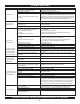
BRANCH
AWG
DISTANCE IN FEET FROM MOTOR TO SUPPLY
MAX. LOAD
FUSE
MIN. WIRE
0-100 101-200 201-300 301-400 401-500
MOTOR HP VOLTS AMP RATING AMP SIZE (mm
2
) AWG WIRE SIZE (mm
2
)
1/2 115/230 10.6/6.5 15/15 12/14 (3/2) 12/14 (8.4/2) 8/14 (2/2) 6/14 (14/2) 6/12 (14/3) 4/10 (21/5.5)
3/4 115/230 11/6.6 20/15 10/14 (5.5/2) 12/14 (8.4/2) 8/14 (8.4/2) 6/12 (14/3) 4/10 (21/5.5) 4/10 (21/5.5)
1 115/230 11.8/6.7 25/15 10/14 (5.5/2) 6/14 (14/2) 8/14 (8.4/2) 6/12 (14/3) 4/10 (21/5.5) 4/10 (21/5.5)
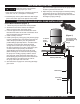
ELECTRICAL
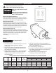
Motor Switch Settings (Figure 8)
Motors are designed to run on either 115 volt or 230 volt
current. Be sure the motor’s wires are attached properly to
the motor’s control panel for the voltage required.
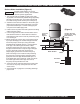
Wiring Pressure Switch
Attach the wires from the power source to the pressure
switch following the directions provided under the cover of
the pressure switch, i.e. remove the pressure switch cover
and follow wiring directions under the cover lid. Be sure to
ground wire the pressure switch to the motor.
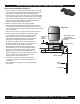
Wiring the Motor (Figure 9)
Attach wires between the pressure switch and the motor
ensuring the wires are connected to the motor for the proper
electrical source voltage, i.e. 115V or 230V- see the wiring
diagrams in this manual or under the cover of the motor.
Ensure to ground the pressure switch
to the motor.
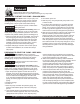
Disconnect power before working on
pump, motor, pressure switch or wiring
Motor may be hot. Allow to cool 20
minutes.
Water pressure may have built up in
the pump, pipes and/or tank. Drain
water to relieve pressure.
!
!
Wiring
Risk of electric shock.
Can shock, burn or kill.
1. To avoid dangerous or fatal electrical shock, turn OFF
power to motor before working on electrical
connections.
2. Ground motor before connecting to electrical power
supply. Failure to ground motor can cause severe or
fatal electrical shock hazard.
3. Supply voltage must be within +/- 10% of nameplate
voltage. Incorrect voltage can cause re or damage
motor and voids warranty. If in doubt consult a
licensed electrician.
4. Use wire size specied in Wiring Chart (below). If
possible, connect pump to a separate branch circuit
with no other appliances on it.
5. Do not ground to a gas supply line.
6. Wire motor according to diagram on motor nameplate.
If nameplate diagram diers from diagrams above,
follow nameplate diagram.
7. If this procedure or the wiring diagrams are
confusing, consult a licensed electrician.
Wiring Chart Recommended Wire and Fuse Sizes for 115 and 230 volts
(Figure 9)
Remove Motor
End Plate
Figure 8