EcoFlow Solar Tracker User Manual
DISCLAIMER Read all safety tips, warning messages, terms of use, and disclaimers carefully. Refer to the terms of use and disclaimer at https://ecoflow.com/pages/terms-of-use and stickers on the product before use. Users take full responsibility for all usage and operations. Familiarize yourself with the related regulations in your area. You are solely responsible for being aware of all relevant regulations and using EcoFlow products in a way that is compliant.
CONTENTS 1. Assembly Instructions 1 1.1 What's in the box 1 1.2 Installation 2 --1.2.1 Solar Tracker Instrallation 2 --1.2.2 Using foldable solar panels 6 --1.2.3 Using rigid solar panels 8 1.3 Disassembly 11 1.4 Transportation 12 1.5 Using The Solar Tracker 13 --1.5.1 Positioning the Solar Tracker 13 --1.5.2 Turning on and off 14 --1.5.3 Emergency stop button 14 --1.5.4 Operation Modes 14 2. Specifications 15 2.1 Specifications 15 2.2 Built-in battery 15 3.
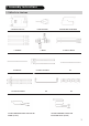
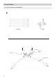
1. Assembly Instructions 1.1 What's in the box CONTROL MODULE L-FEMALE A1-MIDDLE A3-LEFT A3-RIGHT SOLAR CHARGING CABLE FOR SOLAR PANEL (0.92ft) LIGHT SENSOR L-MALE A1-LEFT A1-RIGHT A4 MOTORIZED LEVER ARM B-LEFT B-RIGHT A2 A5 SOLAR CHARGING CABLE FOR ECOFLOW UNITS (9.
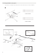
1.2 Installation 1.2.
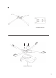
2 CONTROL MODULE CONTROL MODULE 3
3 A4 A2 MOTORIZED LEVER ARM A2 A4 4 MOTORIZED LEVER ARM
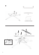
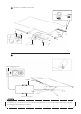
4 B-LEFT B-RIGHT B-LEFT B-RIGHT 5
1.2.2 Using foldable solar panels *If you plan to use foldable solar panels, please continue with step 5 to 7 to finish installation.
6 Attach the foldable solar panel. 0.92ft 7 Solar Charging Port 9.84ft MC4 Connectors NOTE Long press the power button. The indicator light will turn on. The solar tracker will begin rotating according to the lighting conditions.
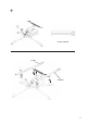
1.2.3 Using rigid solar panels *If you plan to use the rigid solar panels, please continue with step 8 to 11 to detach the folding bars and finish installation.
9 A5 9
10 0.92ft 11 Solar Charging Port 9.84ft MC4 Connectors NOTE Long press the power button; The indicator light will turn on. The solar tracker will begin rotating according to the lighting conditions.
1.3 Disassembly 1 A1-LEFT A1-RIGHT A3-LEFT A3-RIGHT NOTE Please fold A3-LEFT and A3-RIGHT first, and then fold A1-LEFT and A1-RIGHT. 2 Detach the control module from the base stand. Fold the legs of the base.
1.
1.5 Using The Solar Tracker 1.5.1 Positioning the Solar Tracker The Solar Tracker can rotate 345° therefore it has a 15° blind spot. That means if you're in the northern hemisphere, you should position the front of the solar tracker to the east with a slight northern tilt. If you're in the southern hemisphere, you should position the front of the solar tracker to the east with a slight southern tilt.
1.5.2 Turning on and off Turn on the tracker by pressing the power button for 3 seconds. A long beep indicates that it is powered on. Turn off the tracker by pressing the power button for 3 seconds. A long beep indicates that it is powered off. The stand will rotate back to its starting position, and then shut down automatically. NOTE Please note that the Solar Tracker won't be powered off if the solar panel is still connected and getting solar power. 1.5.
2. Specifications 2.1 Specifications Weight 25KG Load capacity 25KG Pitch axis range 0–85° Yaw axis range 0–345° Size 2.5 × 1.5 × 1.5m (Minimum 2.5 × 1.1 ×1.1m) APP Supported Built-in battery capacity 5000mAh Waterproof IP54 Wind resistance 6 Strong Breeze 2.2 Built-in battery* Battery chemistry NCM Shelf life 1 year(after full charge) Lifespan 500 cycles to 80% capacity Operating temperature -10°C~40°C (optimal: 25°C) *The built-in battery can be recharged from solar power.
4. Light Indicators 4.1 Power Status Indicator Power on: Fast flashing (flash for 0.1s every 0.2s) Working: Slow flashing (flash for 1s every 0.5s) Sleep: Always on NOTE Please note that the Solar Tracker won't be powered off if the solar panel is still connected and getting solar power. The light indicator will keep short flashing (flash for 1s every 0.1s). 4.
17