Built-In BBQ Grills Grill Models: GRL270IBNG / GRL270IBLP GRL300IBNG / GRL300IBLP GRL360IBBNG / GRL360IBBLP GRL420IBBNG / GRL420IBBLP Owner’s Manual For more information on other great EdgeStar products on the web, go to https://www.edgestar.com V2.
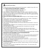
Important Safety Information Improper handling can cause serious damage to the EdgeStar grill and/or injury to the user. This grill is designed for domestic use only. Do not use the unit for industrial or commercial use. Do not use in any enclosed areas, including buildings and garages. Any other use may invalidate the warranty. Please review the ratings label for technical data related to this unit.
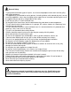
Gas and Electrical Safety This gas grill must be installed in accordance with all local codes. In addition, the gas grill(s) must be installed in accord with the following codes, as applicable: National Fuel Gas Code, ANSI Z223.1 / NFPA 54 Natural Gas and Propane Installation Code, CSA B149.1 Propane Storage and Handling Code, CSA B149.
General Safety To prevent back and other types of injuries, use at least two people to move and install the grill(s) and grilling equipment. This appliance is not intended for use by persons, including children, with reduced physical, sensory or mental capabilities, unless they have been given supervision or instruction concerning the use of the appliance by the person(s) responsible for their safety. Install the gas grill(s) in a well-ventilated area.
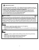
PROPANE GAS SAFETY Your propane gas grill (models GRL****LP) is designed to operate on propane gas only at a pressure regulated at 11 inches water column (WC) when equipped with the correct propane orifices on the valves and a propane regulator on the supply line. EdgeStar LP grills are designed to be used with a standard 20 lb. (9.1kg) Department of Transportation (DOT) approved LP cylinder. No tanks larger than 20 lbs. are to be used.
NATURAL GAS SAFETY Your natural gas grill (models GRL****NG) is designed to operate on natural gas only at a pressure regulated at 4 inches water column (WC) when equipped with the correct natural gas orifices on the valves and a natural gas regulator on the supply line. Burners must be inspected and cleaned before each use. Beware of Spiders Spiders and small insects occasionally spin webs or make nests in the burners during warehousing, transit, and/or after long period of not using the grill.
Table of Contents IMPORTANT SAFETY INFORMATION ................................................................................................................I INTRODUCTION ............................................................................................................................................. 2 PARTS IDENTIFICATION .................................................................................................................................. 3 GRILL DIMENSIONS .......................
Introduction Thank you for purchasing this EdgeStar gas grill. We hope that this purchase will be the beginning of a lasting and rewarding relationship between you and EdgeStar. We will provide the customer support and exemplary products necessary to nurture that relationship. This manual contains important information regarding the proper installation, use and maintenance of your gas grill. Following this manual will ensure that your product will work at its peak performance and efficiency.
Parts Identification GRL270IBNG / GRL270IBLP GRL300IBNG / GRL300IBLP (Two Burner Gas Grills) 3
Part Name Temperature Gauge Hood Handle Internal Lights Back Cover Rear Infrared Burner Warming Rack Infrared Igniter Cover Igniter Cover Stainless Steel Flexline Stainless Steel Drip Tray Firebox Infrared (IR) Burner Cast Burner Gas Control Knob Knob Bezel Light Switch Control Panel (Face Plate) Transformer Electrode Wire LED Lights Main Burner Valve Rear Infrared Burner Valve Gas Manifold Assembly Heat Separator (Zone Divider) Flame Tamer Cooking Grates Rotisserie Motor Motor Bracket Rotisserie Spit Rod F
GRL360IBBNG / GRL360IBBLP GRL420IBBNG / GRL420IBBLP (Three Burner Gas Grills) 5
Part Name Temperature Gauge Hood Handle Internal Lights Back Cover Rear Infrared Burner Warming Rack Infrared Igniter Cover Igniter Cover Stainless Steel Flexline Stainless Steel Drip Tray Firebox Infrared (IR) Burner Cast Burner Gas Control Knob Knob Bezel Light Switch Control Panel (Face Plate) Transformer Electrode Wire LED Lights Main Burner Valve Rear Infrared Burner Valve Gas Manifold Assembly Heat Separator (Zone Divider) Flame Tamer Cooking Grates Rotisserie Motor Motor Bracket Rotisserie Spit Rod F
Grill Dimensions GRL270IBNG / GRL270IBLP 7
GRL300IBNG / GRL300IBLP 8
GRL360IBBNG / GRL360IBBLP 9
GRL420IBBNG / GRL420IBBLP 10
Island / Cabinet Cutout Dimensions Do not store extra propane or butane tanks in proximity to your gas grill. All BBQ islands must be manufactured from non-combustible material(s). Minimum clearance to combustible construction material(s) is 24” from the back and sides. Built-in islands and cabinets must be equipped with vents to allow for proper ventilation and combustion. 4” x 6” vents or larger are required.
Maintaining Adequate Ventilation When building a gas grill into outdoor cabinetry or an island, it is important to maintain proper ventilation. Ventilation is required to prevent the build-up of gas, which could ultimately lead to improper performance of the gas grill; damage to the grill; fire, explosion, or injury to the user. Always make sure that there is proper ventilation and that all flammable materials are placed at least 24 inches away from the grill on all side.
Installing the Gas Grill Tip: Gather the model and serial number from the product label and write them down before installing the gas grill(s). Notes About Installation The gas grill should be installed in accordance with all local code requirements in addition to the National Fuel Gas Code, ANSI Z223.1 / NFPA 54. Installation by a professional is highly recommended for proper placement and functionality.
Liquid Propane (LP) Installation and Requirements: Grills operated with LP fuel must be installed with the supplied LP regulator. EdgeStar LP grills are designed to be used with a standard 20 lb. Department of Transportation (DOT) approved LP tank. No tanks larger than 20 lbs. are to be used. The tank must be marked in accordance with the latest DOT specification for LP gas tanks: Specifications for LP gas Cylinders (DOT CFR49).
To Connect the LP Gas Supply: 1. Ensure the 20 lb. LP tank valve is fully closed. To do so, make sure the tank handle is turned all the way clockwise. You should not hear a hissing noise or smell propane. 2. All gas control (burner) knobs must be in the off position. 3. Align the 3/8” brass coupling nut with the LP tank threads; turn the coupling nut clockwise by hand. Note that the fittings have flared ends and do not require any modifications or sealant.
6. Once you have confirmed that all connections are secure and there are no gas leaks, you may proceed with normal use of your grill. All connection points must be free from gas leaks before first use of the gas grill. 7. A reminder to always close the LP tank valve [by turning the handle clockwise] when the grill is not in use.
Natural Gas (NG) Installation and Requirements: Ensure that the natural gas supply line is fitted with a shut-off valve that can be easily accessed in the event that shutoff at the source is required. Grills operated with NG fuel must be installed with the NG regulator supplied with your EdgeStar grill. EdgeStar NG grills are equipped with an NG regulator set to 4 inches water column. This regulator is for NG only. The standard fitting connector for an NG supply is 1/2”.
18
Checking for Gas Leaks At least once every six months, and any time a tank is disconnected and reconnected, perform a leak test. Additionally, any time any components including the gas supply lines or the regulator are replaced, perform a leak test. Never use the grill without testing for gas leaks first. WARNING: Do not test for gas leaks with an open flame. When testing for leaks, make sure all gas control knobs are in the off position.
Electrical Requirements ELECTRIC SHOCK HAZARD! Plug into a grounded 3-prong outlet. Never remove the grounding prong from the plug. Never use an adapter to bypass the grounding prong. DO NOT use an extension cord. Failure to follow these instructions can result in fire, electrical shock, or death. Before you install your gas grill into its final location, it is important to make sure you have the proper electrical connection.
Recommended Grounding Method For your personal safety, this appliance must be grounded. It is equipped with a power supply cord having a 3-prong grounding plug. To minimize possible shock hazard, the cord must be plugged into a mating 3-pronged wall socket, and grounded in accordance with the National Electrical Code and local codes and ordinances.
Included Cooking Components CAUTION: The included ceramic flame tamers are only meant for use with the main cast burners. Do not install the ceramic flame tamers over the included infrared burner(s) as they will be damaged. For information on purchasing additional / substitute burners, please visit www.edgestar.com.
Operation Important: You must always have the grill hood open when lighting the gas grill. Otherwise, you risk build-up of gas and possible fire or explosion. Important: To avoid risk of injury, always keep your face and body as far away as possible from the grill when lighting. As you proceed to operate the grill, note that surfaces may be hot and pose a burn hazard. Take care around the grill and make sure to never leave it unattended. Children should not operate the grill.
Lighting the Burner(s) 1. Make sure you have observed all safety warnings in this manual. Follow the instructions for connecting the gas supply. NEVER turn on the grill without testing for leaks first. Keep all body parts as far away from the grill as possible. Never smoke while lighting the grill. 2. Open the grill hood. 3. With all gas control (burner) knobs in the OFF position, open the gas supply. 4.
Manually Lighting the Burner(s) Important: If you have tried lighting your burners using the Piezo-style system, wait at least five (5) minutes before manually lighting the burners. Leave the hood open and allow gas to dissipate to avoid a possible hazard. 1. Make sure you have observed all safety warnings in this manual. Follow the instructions for connecting the gas supply. NEVER turn on the grill without testing for leaks first. Keep all body parts as far away from the grill as possible.
6. Push the gas control (burner) knob in, and rotate counterclockwise to the “High” position marking on the knob. 7. Repeat steps 4-6 for each main burner you need to light. 8. Close the lid and allow the burners to run on “High” for about five minutes to burn off extra gas and residue. 9. Open the lid and adjust the burner knobs to your desired cooking temperature. 10. Safely dispose of the match(es) and replace the manual lighting clip extension on the drip tray.
Manually Lighting the Rear Burner Important: If you tried lighting the rear burner with the burner knob and were unable, wait at least five (5) minutes before manually lighting the burner. Leave the hood open and allow gas to dissipate to avoid a possible hazard. 1. Make sure you have observed all safety warnings in this manual. Follow the instructions for connecting the gas supply. NEVER turn on the grill without testing for leaks first. Keep all body parts as far away from the grill as possible. 2.
Cleaning and Maintenance Caution: Always ensure that the gas supply is fully turned off prior to performing any cleaning and maintenance on your grill. Never attempt to clean parts of the grill while they are still hot. Periodic cleaning and proper maintenance will ensure efficiency, top performance, and long life. Additionally, proper preventive maintenance is required for your own safety. Use a pipe cleaner or wire to clear any blockages in the tubes that lead into the burners.
2. Use a bristled brush and run it through the orifices of the burner several times. 3. Go over the exterior of the burner with a wire brush several times to loosen debris and residue. You may also wipe it with a terry cloth or damp rag without using any chemicals. For stubborn scale, you may use a scraper. 4. Look at all burner ports (the small openings) and run a pipe cleaner or thin wire through them. 5. Analyze the burner for corrosion and any damage caused by corrosion. 6.
Inspecting / Adjusting the Air Shutter If necessary, the gas to air mixture feeding to the main cast burners can be adjusted. With the main burner removed from the firebox, loosen the screw shown in the image below. Rotate the shutter clip. Tighten the screw and reinstall the burner. Note: Before adjusting the air shutter, ensure that the burner has been cleaned. Note: The ideal flame coming off of the main burner is 1” – 1-1/2” tall. The color should be blue with yellow peaks.
Cleaning the Drip Tray The removable drip tray will collect grease as you use your grill. Inspect the drip tray frequently to ensure that grease and debris do not build up. The drip tray can be wiped with a warm soapy water mixture and a terry cloth. Use a wire brush, if necessary, to loosen hardened grease. Warning: Grease build-up poses a fire hazard. Clean the drip tray regularly.
Cart Dimensions Your EdgeStar grill may be used in a freestanding installation when installed with a cart. Cart dimension cutouts are detailed on the following pages.
Cart for GRL300IBNG / GRL300IBLP (30” Grill Models) 33
Cart for GRL360IBBNG / GRL360IBBLP (36” Grill Models) 34
Cart for GRL420IBBNG / GRL420IBBLP (42” Grill Models) 35
Cart Assembly Instructions 36
37
38
Specifications Note: Technical data and performance information are provided for reference only.
EdgeStar Limited Warranty This product is warranted by EdgeStar to be free from defective workmanship and materials, subject to any conditions set forth as follows: WHAT IS COVERED: LABOR: For a period of NINETY (90) DAYS from the date of original purchase, labor will be performed free of charge at an authorized EdgeStar repair facility. At its option, EdgeStar will repair the product with new or remanufactured parts, or exchange the defective product with a new, refurbished, or remanufactured product.
OBTAINING WARRANTY SERVICE: If you believe your product is defective, contact EdgeStar Customer Support for troubleshooting assistance and warranty service at 1-866-319-5473. Please have your serial number and proof of purchase available. Once an EdgeStar authorized representative has confirmed that your product is defective and eligible for warranty service, the product must be returned to an EdgeStar repair facility.