Introduction................................................................................................................ 3 Features.............................................................................................................................. 3 Minimum Requirements .................................................................................................. 3 Package Content...............................................................................................................
.6 Firewall ...................................................................................................................... 62 2.6.1 Access Control........................................................................................................ 63 2.6.2 URL Blocking ......................................................................................................... 67 2.6.3 Hacker Prevention .................................................................................................
Introduction Congratulations on purchasing this Wireless Broadband Router. This Wireless Broadband Router is a cost-effective IP Sharing Router that enables multiple users to share the Internet through an ADSL or cable modem. Simply configure your Internet connection settings in the Wireless Broadband Router and plug your PC to the LAN port and you're ready to share files and access the Internet.
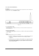
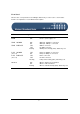
Get to know the Broadband Router Back Panel The diagram (fig1.0) below shows the broadband router’s back panel. The router’s back panel is divided into three sections, LAN, WAN and Reset: Figure 1.0 1) Local Area Network (LAN) The Broadband router’s 4 LAN ports are where you connect your LAN’s PCs, printer servers, hubs and switches etc. 2) Wide Area Network (WAN) The WAN port is the segment connected to your xDSL or Cable modem and is linked to the Internet.
Front Panel On the router’s front panel there are LED lights that inform you of the router’s current status. Below is an explanation of each LED and its description.
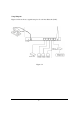
Setup Diagram Figure 1.2 below shows a typical setup for a Local Area Network (LAN). Figure 1.
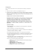
Getting started This is a step-by-step instruction on how to start using the router and get connected to the Internet. 1) Setup your network as shown in the setup diagram above (fig 1.2). 2) You then need to set your LAN PC clients so that it can obtain an IP address automatically. All LAN clients require an IP address. Just like an address, it allows LAN clients to find one another.
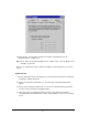
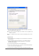
: Reboot the PC. Your PC will now obtain an IP address automatically from your Broadband Router’s DHCP server. Note: Please make sure that the Broadband router’s DHCP server is the only DHCP server available on your LAN. Once you’ve configured your PC to obtain an IP address automatically, please proceed to Step 3 2b) Windows XP 1: Click the Start button and select Settings , then click Network Connections. The Network Connections window will appear. 2: Double-click Local Area Connection icon.
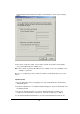
5: Click OK to confirm the setting. Your PC will now obtain an IP address automatically from your Broadband Router’s DHCP server. Note: Please make sure that the Broadband router’s DHCP server is the only DHCP server available on your LAN. Once you’ve configured your PC to obtain an IP address automatically, please proceed to Step 3. 2c) Windows 2000 1: Click the Start button and select Settings , then click Control Panel. The Control Panel window will appear.
automatically and Obtain DNS server address automatically as shown on the following screen. 6: Click OK to confirm the setting. You r PC will now obtain an IP address automatically from your Broadband Router’s DHCP server. Note: Please make sure that the Broadband router’s DHCP server is the only DHCP server available on your LAN. Once you’ve configured your PC to obtain an IP address automatically, please proceed to Step 3.
button to start installing the TCP/IP protocol. You may need your Windows CD to complete the installation. 5: After you install TCP/IP, go back to the Network window. Select TCP/IP from the list of Network Protocols and then click the Properties button. 6: Check each of the tabs and verify the following settings: • IP Address: Select Obtain an IP address from a DHCP server. • DNS: Let all fields are blank. • WINS: Let all fields are blank. • Routing: Let all fields are blank.
3) Once you have configured your PCs to obtain an IP address automatically, the router’s DHCP server will automatically give your LAN clients an IP address. By default the Broadband Router’s DHCP server is enabled so that you can obtain an IP address automatically. To see if you have obtained an IP address, see Appendix A. Note: Please make sure that the Broadband router’s DHCP server is the only DHCP server available on your LAN.
can just configure the General Setup section, since the General Setup/WAN and the Quick Setup Wizard contain the same configurations. Status Information (Chapter 3) The Status Information section is for you to monitor the router’s current status information only. Tools (Chapter 4) If you want to Reset the router (because of problems) or save your configurations or upgrade the firmware then the Tools section is the place to do this.
Access Control, Hacker Attack Prevention, DMZ, Special applications and other functions to meet your LAN requirements. Status Information (Chapter 3) In this section you can see the Broadband router's system information, Internet Connection, Device Status, Security Log and DHCP client Log information. Tools (Chapter 4) This section contains the broadband router’s Tools - Tools include Configuration tools, Firmware upgrade and Reset.
Chapter 1 Quick Setup The Quick Setup section is designed to get you using the broadband router as quick as possible. In the Quick Setup you are required to fill in only the information necessary to access the Internet. Once you click on the Quick Setup Wizard in the HOME page, you should see the screen below. Step 1) Time Zone The Time Zone allows your router to base its time on the settings configured here, this will affect functions such as Log entries and Firewall settings.
Enable Daylight Savings The router can also take Daylight savings into account. If you wish to use this function, you must check/tick the enable box to enable your daylight saving configuration (below). Start Daylight Savings Time Select the period in which you wish to start daylight Savings Time End Daylight Savings Time Select the period in which you wish to end daylight Savings Tim e Click on NEXT to proceed to the next page (step 2) Broadband Type.
Menu Description 1.1 Cable Modem Your ISP will automatically give you an IP address 1.2 Fixed-IP xDSL Your ISP has given you an IP address already 1.3 PPPoE Your ISP requires you to use a Point-to-Point Protocol over Ethernet (PPPoE) connection. 1.4 PPTP Your ISP requires you to use a Point-to-Point Tunneling Protocol (PPTP) connection. Click on one of the WAN type and then proceed to the manual’s relevant sub -section (1.1, 1.2, 1.3 or 1.4). Click on Back to return to the previous screen.
1.1 Cable Modem Choose Cable Modem if your ISP will automatically give you an IP address. Some ISP’s may also require that you fill in additional information such as Host Name and MAC address (see screen below). Note: The Host Name and MAC address section is optional and you can skip this section if your ISP does not require these settings for you to connect to the Internet.
1.2 Fixed-IP xDSL Select Fixed-IP xDSL if your ISP has given you a specific IP address for you to use. Your ISP should provide all the information required in this section. Parameters Description IP This is the IP address that your ISP has given you. Gateway IP This is the ISP’s IP address gateway DNS This is the ISP’s DNS server IP address Subnet Mask Enter the Subnet Mask provided by your ISP (e.g. 255.255.255.0) Click when you have finished the configuration above.
1.3 PPPoE Select PPPoE if your ISP requires the PPPoE protocol to connect you to the Internet. Your ISP should provide all the information required in this section. Parameter Description User Name Enter the User Name provided by your ISP for the PPPoE connection Password Enter the Password provided by your ISP for the PPPoE connection Service Name This is optional. Enter the Service name should your ISP requires it, otherwise leave it blank. MTU This is optional.
Connection Type If you select “Continuous”, the router will always connect to the ISP. If the WAN line breaks down and links again, the router will auto-reconnect to the ISP. If you select “Connect On Demand”, the router will autoconnect to the ISP when someone want to use the Internet and keep connected until the WAN idle timeout. The router will close the WAN connection if the time period that no one is using the Internet exceeds the “Idle Time”.
1.4 PPTP Select PPTP if your ISP requires the PPTP protocol to connect you to the Internet. Your ISP should provide all the information required in this section. Parameter Descriptio n Obtain an IP address automatically The ISP requires you to obtain an IP address by DHCP before connecting to the PPTP server. Use the following IP address The ISP give you a static IP to be used to connect to the PPTP server. IP Address This is the IP address that your ISP has given you to establish a PPTP connection.
Subnet Mask Enter the Subnet Mask provided by your ISP (e.g. 255.255.255.0) Gateway Enter the IP address of the ISP Gateway User ID Enter the User Name provided by your ISP for the PPTP connection. Sometimes called a Connection ID Password Enter the Password provided by your ISP for the PPTP connection PPTP Gateway If your LAN has a PPTP gateway, then enter that PPTP gateway IP address here.
Click when you have finished the configuration above. Congratulations! You have completed the configuration for the PPTP connection. You can start using the router now, if you wish to use some of the advance features supported by this router see chapter 2, 3, 4.
Chapter 2 General Settings Once you click on the General Setup button at the Home Page, you should see the screen below. If you have already configured the Quick Setup Wizard you do NOT need to configure anything thing in the General Setup screen for you to start using the Internet.
Below is a general description of what advance functions are available for this broadband router. Menu Description 2.1 System This section allows you to set the Broadband router’s system Time Zone, Password and Remote Management Administrator. 2.2 WAN This section allows you to select the connection method in order to establish a connection with your ISP (same as the Quick Setup Wizard section) 2.
2.1 System The system screen allows you to specify a time zone, to change the system password and to specify a remote management user for the broadband router. Parameters System Settings Description 2.1.1 Time Zone Select the time zone of the country you are currently in. The router will set its time based on your selection. 2.1.2 Password Settings Allows you to select a password in order to access the web -based management website. 2.1.
Parameter Description Set Time Zone Select the time zone of the country you are currently in. The router will set its time based on your selection. Enable Daylight Savings The router can also take Daylight savings into account. If you wish to use this function, you must check/tick the enable box to enable your daylight saving configuration (below).
Parameters Current Password Description New Password Enter your new password Re-Enter Password for Verification Enter your new password again for verification purposes Enter your current password for the remote management administrator to login to your Broadband router.
Parameters Host Address Description This is the IP address of the host in the Internet that will have management/configuration access to the Broadband router from a remote site. This means if you are at home and your home IP address has been designated the Remote Management host IP address for this router (located in your company office), then you are able to configure this router from your home. If the Host Address is left 0.0.0.
Port The port number of remote management web interface. Enabled Select “Enabled” to enable the remote management function. Click at the bottom of the screen to save the above configurations.
2.2 WAN Use the WAN Settings screen if you have already configured the Quick Setup Wizard section and you would like to change your Internet connection type. The WAN Settings screen allows you to specify the type of WAN port connect you want to establish with your ISP. In the WAN Settings screen you can also specify the router to act as a Bridge. The WAN settings offer the following selections for the router’s WAN port, Dynamic IP, PPPoE, PPTP, Static IP Address, Bridge , DNS and DDNS. Parameters 2.2.
2.2.8 DNS You can specify a DNS server that you wish to use 2.2.9 DDNS You can specify a DDNS server that you wish to use and configure the user name and password provided by you DDNS service provider. Once you have made a selection, click at the bottom of the screen and proceed to the manual’s relevant sub-section 2.2.1 Dynamic IP Choose the Dynamic IP selection if your ISP will automatically give you an IP address.
2.2.5 L2TP Select L2TP if your ISP requires the L2TP protocol to connect you to the Internet. Your ISP should provide all the information required in this section. Parameter Description Obtain an IP address automatically The ISP requires you to obtain an IP address by DHCP before connecting to the L2TP server. Use the following IP address The ISP give you a static IP to be used to connect to the L2TP server. IP Address This is the IP address that your ISP has given you to establish a L2TP connection.
(e.g. 255.255.255.0) Gateway Enter the IP address of the ISP Gateway User ID Enter the User Name provided by your ISP for the PPTP connection. Sometimes called a Connection ID Password Enter the Password provided by your ISP for the PPTP connection L2TP Gateway If your LAN has a L2TP gateway, then enter that L2TP gateway IP address here.
2.2.6 Telstra Big Pond Select Telstra Big Pond if your ISP requires the Telstra Big Pond protocol to connect you to the Internet. Your ISP should provide all the information required in this section. Telstra Big Pond protocol is used by the ISP in Australia.
2.2.7 Bridge The bridge mode screen allows you to set your Broadband router to bridge mode and allows you to assign an IP address for management purposes. When the bridge mode is selected, the router in effect becomes a switch, transferring packets from the WAN port to the LAN port and vice versa without any NAT involvement. In bridge mode, the original WAN MAC is ignored, and the original LAN MAC address will be used as the MAC address.
Example: Bridge Mode The diagram below demonstrates how the Bridge mode can be used. The router basically becomes a hub/switch allowing you to connect LAN clients to your Local Area Network.
2.2.8 DNS A Domain Name System (DNS) server is like an index of IP addresses and Web addresses. If you type a Web address into your browser, such as www.router.com, a DNS server will find that name in its index and the matching IP address. Most ISPs provide a DNS server for speed and convenience. If your Service Provider connects you to the Internet with dynamic IP settings, it is likely that the DNS server IP address is provided automatically.
2.2.9 DDNS DDNS allows you to map the static domain name to a dynamic IP address. You must get an account, password and your static domain name from the DDNS service providers. This router supports DynDNS and TZO.
2.3 LAN The LAN Port screen below allows you to specify a private IP address for your router’s LAN ports as well as a subnet mask for your LAN segment. Parameters Default Description LAN IP IP address 192.168.2.1 This is the router’s LAN port IP address (Your LAN clients default gateway IP address) IP Subnet Mask 255.255.255.
802.1d Spanning Tree Disabled If 802.1d Spanning Tree function is enabled, this router will use the spanning tree protocol to prevent from network loop happened in the LAN ports. DHCP Server You can enable or disable the DHCP server. By enabling the DHCP server the router will automatically give your LAN clients an IP address.
2.4 Wireless Wireless Access Point builds a wireless LAN and can let all PCs equipped with IEEE 802.11b wireless network adaptor connect to your Intranet. It supports WEP encryption to enhance the security of your wire less network. Parameters Default Description Enable or disable Enable You can select to enable or disable the wireless access point module of this router. Wireless module Click at the bottom of the screen to save the above configurations.
2.4.1 Basic Settings You can set parameters that are used for the wireless stations to connect to this router. The parameters include Alias Name, ESSID and Channel. Parameters Default Alias Name Description The alias name of this router. ESSID default Channel Number 11 This is the name of the wireless LAN. All the devices in the same wireless LAN should have the same ESSID. The channel used by the wireless LAN. All devices in the same wireless LAN should use the same channel.
2.4.2 Advanced Settings You can set advanced wireless LAN parameters of this router. The parameters include Authentication Type, Fragment Threshold, RTS Threshold, Beacon Interval, Preamble Type … … You should not change these parameters unless you know what effect the changes will have on this router. Parameters Authentication Type Default Description There are two authentication types: "Open System" and "Shared Key".
Fragment Threshold "Fragment Threshold" specifies the maximum size of packet during the fragmentation of data to be transmitted. If you set this value too low, it will result in bad performance. RTS Threshold When the packet size is smaller the RTS threshold, the wireless router will not use the RTS/CTS mechanism to send this packet. Beacon Interval The interval of time that this wireless router broadcast a beacon. Beacon is used to synchronize the wireless network.
2.4.3 Encryption By using Encryption, the data will be transmitted securely over the wireless network. You have to setup the same encryption key both on your router and wireless client devices. Parameters Default Description WEP Mode Disabled You can select the WEP key length for encryption, 64-bit or 128-bit. Larger WEP key length will provide higher level of security, but the throughput will be lower. You also can select Disabled to transmit data without encryption.
Parameters Default Description Key Format You may select to select ASCII Characters (alphanumeric format) or Hexadecimal Digits (in the "A-F", "a-f" and "0-9" range) to be the WEP Key. For example: ASCII Characters: guest Hexadecimal Digits: 12345abcde Key Length You may disable or enable the WEP function from the setting item. The selections in the setting item are changed based on the key format. Key 1 - Key 4 The WEP keys are used to encrypt data transmitted in the wireless network.
64-bit WEP: input 10-digit Hex values (in the "AF", "a-f" and "0-9" range) or 5-digit ASCII character as the encryption keys. 128-bit WEP: input 26-digit Hex values (in the "A-F", "a-f" and "0-9" range) or 10 -digit ASCII characters as the encryption keys. Default Key Select one of the four keys to encrypt your data. Only the key you select it in the "Default key" will take effect. Click at the bottom of the screen to save the above configurations.
2.5 NAT Network Address Translation (NAT) allows multiple users at your local site to access the Internet through a single Public IP Address or multiple Public IP Addresses. NAT provides Firewall protection from hacker attacks and has the flexibility to allow you to map Private IP Addresses to Public IP Addresses for key services such as Websites and FTP. Parameter 2.5.1 Port Forwarding Description 2.5.2 Virtual Server You can have different services (e.g. email, FTP, Web etc.
Click on one of the three NAT selections and proceed to the manual's relevant subsection.
2.5.1 Port Forwarding The Port Forwarding allows you to re-direct a particular range of service port numbers (from the Internet/WAN Ports) to a particular LAN IP address. It help you to host some servers behind the router NAT firewall. Parameter Description Enable Port Forwarding Enable Port Forwarding Private IP This is the private IP of the server behind the NAT firewall. Note: You need to give your LAN PC clients a fixed/static IP address for Port Forwarding to work properly.
Add Port Forwarding into the table Fill in the "Private IP", “Type”, “Port Range” and "Comment" of the setting to be added and then click "Add". Then this Port Forwarding setting will be added into the "Current Port Forwarding Table" below. If you find any typo before adding it and want to retype again, just click "Clear" and the fields will be cleared.
2.5.2 Virtual Server Use the Virtual Server function when you want different servers/clients in your LAN to handle different service/Internet application type (e.g. Email, FTP, Web server etc.) from the Internet. Computers use numbers called port numbers to recognize a particular service/Internet application type. The Virtual Server allows you to re-direct a particular service port number (from the Internet/WAN Port) to a particular LAN private IP address and its service port number.
Type Select the port number protocol type (TCP, UDP or both). If you are unsure, then leave it to the default both protocol. Public Port Enter the service (service/Internet application) port number from the Internet that will be re-directed to the above Private IP address host in your LAN Note: Virtual Server function will have priority over the DMZ function if there is a conflict between the Virtual Server and the DMZ settings. Comment The description of this setting.
Example: Virtual Server The diagram below demonstrates one of the ways you can use the Virtual Server function. Use the Virtual Server when you want the web server located in your private LAN to be accessible to Internet users. The configuration below means that any request coming form the Internet to access your web server will be translated to your LAN’s web server (192.168.2.2). Note: For the virtual server to work properly Internet/remote users must know your global IP address.
2.5.3 Special Applications Some applications require multiple connections, such as Int ernet games, video conferencing, Internet telephony and others. In this section you can configure the router to support multiple connections for these types of applications. Parameters Description Enable Trigger Port Enable the Special Application function.
Public Type Select the Inbound port protocol type: “TCP”, “UDP” or both Comment The description of this setting. Popular applications This section lists the more popular applications that require multiple connections. Select an application from the Popular Applications selection. Once you have selected an application, select a location (1-10) in the Copy to selection box and then click the Copy to button.
router will allow incoming packets for ports 2300-2400 and 47624 to be directed to that user. Note: Only one LAN client can use a particular special application at a time.
2.5.4 ALG Settings You can select applications that need “Application Layer Gateway” to support. Parameters Enable Default Description You can select to enable “Application Layer Gateway”, then the router will let that application correctly pass though the NAT gateway. Click at the bottom of the screen to save the above configurations.
2.6 Firewall The Broadband router provides extensive firewall protection by restricting connection parameters, thus limiting the risk of hacker attack, and defending against a wide array of common Internet attacks. However, for applications that require unrestricted access to the Internet, you can configure a specific client/server as a Demilitarized Zone (DMZ). Note: To enable the Firewall settings select Enable and click Apply Parameters Description 2.6.
2.6.1 Access Control If you want to restrict users from accessing certain Internet applications/services (e.g. Internet websites, email, FTP etc.), then this is the place to set that configuration. Access Control allows users to define the traffic type permitted in your LAN. You can control which PC client can have access to these services. Parameters Description Filter client PCs by IP Fill “IP Filtering Table ” to filter PC clients by IP.
Add PC Fill in “Client PC MAC Address” and “Comment” of the PC that is allowed to access the Internet, and then click “Add”. If you find any typo before adding it and want to retype again, just click "Reset" and the fields will be cleared. Remove PC If you want to remove some PC from the "MAC Filtering Table", select the PC you want to remove in the table and then click "Delete Selected". If you want remove all PCs from the table, just click "Delete All" button.
Client PC Description The description for this client PC rule. Client PC IP Addresses Enter the IP address range that you wish to apply this Access Control rule. This is the user’s IP address(es) that you wish to setup an Access Control rule. You can select a range of users simply by inputting the starting users’ IP address and the last user’s IP address in the appropriate boxes. If you want to select only one user then input the user’s IP address in both boxes.
Example: Access Control In the example below, LAN client A can only access websites that use Port 80. However, LAN client B is able to access websites and any other service that uses ports between 80 and 999.
2.6.2 URL Blocking You can block access to some Web sites from particular PCs by entering a full URL address or just keyword of the Web site. Parameters Description Enable URL Blocking Enable/disable URL Blocking Add URL Keyword Fill in “URL/Keyword” and then click “Add”. You can enter the full URL address or the keyword of the web site you want to block. If you find any typo before adding it and want to retype again, just click "Reset" and the field will be cleared.
You can now configure other advance sections or start using the router (with the advance settings in place) 68
2.6.3 Hacker Prevention The Broadband router's firewall can block common hacker attacks, including Denial of Service, Ping of Death, Port Scan and Sync Flood. If Internet attacks occur the router can log the events. Parameters Description Intrusion Detection Feature Ping of Death Protections from Ping of Death attack Discard Ping From WAN The router’s WAN port will not respond to any Ping requests Port Scan Protection the router from Port Scan.
2.6.4 DMZ If you have a local client PC that cannot run an Internet application (e.g. Games) properly from behind the NAT firewall, then you can open the client up to unrestricted two-way Internet access by defining a DMZ Host. The DMZ function allows you to re-direct all packets going to your WAN port IP address to a particular IP address in your LAN. The difference between the virtual server and the DMZ function is that the virtual server re-directs a particular service/Internet application (e.g.
Note: You need to give your LAN PC clients a fixed/static IP address for DMZ to work properly.
Chapter 3 Status The Status section allows you to monitor the current status of your router. You can use the Status page to monitor: the connection status of the Broadband router's WAN/LAN interfaces, the current firmware and hardware version numbers, any illegal attempts to access your network, and information on all DHCP client PCs currently conn ected to your network. Parameters Description 3.1 Status and Information Shows the router’s system information 3.
3.
3.2 Internet Connection View the Broadband router’s current Internet connection status and other related information Parameters Description Internet Connection This page displays whether the WAN port is connected to a Cable/DSL connection. It also displays the router’s WAN port: WAN IP address, Subnet Mask, and ISP Gateway as well as the Primary DNS and Secondary DNS being used.
3.3 Device Status View the Broadband router’s current configuration settings. The Device Status displays the configuration settings you’ve configured in the Quick Setup Wizard/General Setup section. Parameters Description Device Status This page shows the Broadband router’s current device settings. This page displays the Broadband router LAN port’s current LAN IP Address and Subnet Mask. It also shows whether the DHCP Server and Firewall functions are enabled/disabled.
3.4 Security Log View any attempts that have been made to illegally gain access to your network. Parameters Security Log Description This page shows the current security log of the Broadband router. It displays any illegal attempts to access your network. At the bottom of the page, the security log can be saved to a local file for further processing or the security log can be cleared or it can be refreshed to get the most updated situation.
3.5 Active DHCP Client Table View your LAN client's information that is currently linked to the Broadband router's DHCP server Parameters Description DHCP Client Log This page shows all DHCP clients (LAN PCs) currently connected to your network. The “Active DHCP Client Table” displays the IP address and the MAC address and Time Expired of each LAN Client.
3.6 Statistics View the statistics of packets sent and received on WAN, LAN and Wireless LAN. Parameters Description Statistics Shows the counters of packets sent and received on WAN, LAN and Wireless LAN.
Chapter 4 Tool This page includes the basic configuration tools, such as Configuration Tools (save or restore configuration settings), Firmware Upgrade (upgrade system firmware) and Reset. Parameters Description 4.1 Configuration Tools You can save the router’s current configuration, restore the router’s saved configuration files and restore the router’s factory default settings 4.2 Firmware Upgrade This page allows you to upgrade the router’s firmware 4.
4.1 Configuration Tools The Configuration Tools screen allows you to save (Backup) the router’s current configuration setting. Saving the configuration settings provides an added protection and convenience should problems occur with the router and you have to reset to factory default. When you save the configuration setting (Backup) you can re-load the saved configuration into the router through the Restore selection.
4.2 Firmware Upgrade This page allows you to upgrade the router’s firmware Parameters Description Firmware Upgrade This tool allows you to upgrade the Broadband router’s system firmware. To upgrade the firmware of your Broadband router, you need to download the firmware file to your local hard disk, and enter that file name and path in the appropriate field on this page. You can also use the Browse button to find the firmware file on your PC.
4.3 Reset You can reset the router’s system should any problem exist. The reset function essentially Re-boots your router’s system Parameters Description Reset In the event that the system stops responding correctly or in some way stops functioning, you can perform a reset. Your settings will not be changed. To perform the reset, click on the button. You will be asked to confirm your decision. The reset will be complete when the power light stops blinking.
Appendix A How to Manually find your PC’s IP and MAC address 1) In Window’s open the Command Prom pt program 2) Type Ipconfig /all and • • • Your PC’s IP address is the one entitled IP address (192.168.1.77) The router’s IP address is the one entitled Default Gateway (192.168.1.
Glossary Bridge: A bridge is an intelligent, internetworking device that forwards or filters packets between different networks based on data link layer (MAC) address information. Default Gateway (Router): Every non-router IP device needs to configure a default gateway’s IP address. When the device sends out an IP packet, if the destination is not on the same network, the device has to send the packet to its default gateway, which will then send it out towards the destination.
ISP Gateway Address: (see ISP for definition). The ISP Gateway Address is an IP address for the Internet router located at the ISP's office. ISP: Internet Service Provider. An ISP is a business that provides connectivity to the Internet for individuals and other businesses or organizations. LAN: Local Area Network. A LAN is a group of computers and devices connected together in a relatively small area (such as a house or an office). Your home network is considered a LAN.
Subnet Mask: A subnet mask, which may be a part of the TCP/IP information provided by your ISP, is a set of four numbers (e.g. 255.255.255.0) configured like an IP address. It is used to create IP address numbers used only within a particular network (as opposed to valid IP address numbers recognized by the Internet, which must be assigned by InterNIC). TCP/IP, UDP: Transmission Control Protocol/Internet Protocol (TCP/IP) and Unreliable Datagram Protocol (UDP).