Sliding glass door Series 5Xpt Installation Instructions Part NO.
5XPT SLIDING GLASS DOOR INSTALLATION INSTRUCTIONS TABLE OF CONTENTS Page I. II. Sliding Glass Door General Overview A. General Notes 3 B. Construction Notes 4 C. Building Codes 5 D. Perimeter Anchorage Considerations 6 E. General Sliding Panel Inspection 7 General Perimeter Preparation for the Door Frame A. Opening Condition Verification III. Perimeter Accessory Fabrication for Assembled Doors A. Subhead Installation 9 B. Sill Starter Installation IV.
5XPT SLIDING GLASS DOOR INSTALLATION INSTRUCTIONS These recommendations are for general erection procedures only. For actual job conditions, see the details on the shop drawings. For perimeter anchor type and spacing, refer to the approved shop drawings or consult the project design professional. SECTION I: Sliding Glass Door General Overview Sliding Glass Doors are a factory glazed product with unassembled main frames and must be handled with care.
5XPT SLIDING GLASS DOOR INSTALLATION INSTRUCTIONS B. Construction Notes 1. Reference Shop Drawings a. Check the shop drawings and installation instructions to become thoroughly familiar with the project. The shop drawings take precedence and include specific details for the project. The installation instructions are general in nature and cover most common conditions. 2. Check Openings a. Make certain that construction, which will receive the material, is in accordance with the contract documents.
XPT SLIDING GLASS DOOR INSTALLATION INSTRUCTIONS 10. Protective Threshold Cover The threshold is supplied with a protective cover to help eliminate damage to the threshold and weather-strip by the construction trades. This cover will need to be removed to allow the door to achieve full water performance. Water may overflow the sill with this protective cover in place. C. Building Codes Note: Glass and glazing codes governing the design and use of products vary widely.
5XPT SLIDING GLASS DOOR INSTALLATION INSTRUCTIONS D. Perimeter Anchorage Considerations 1. From the approved shop drawings, determine the size, type, and quantity of perimeter fasteners required. EFCO will provide fasteners for EFCO material to EFCO material only. All perimeter fasteners are Not by EFCO and should be purchased prior to arriving at the job site. (If subframe is used, please refer to the Subframe Installation sheets.
5XPT SLIDING GLASS DOOR INSTALLATION INSTRUCTIONS 2. Perimeter anchors should never penetrate a tank or tubular shape at a door sill. Any penetration of the frame must be visible for sealing purposes. 3. Blocking must be of sufficient size and shape to support the frame at all anchorage locations. The blocking must prevent the anchorage fasteners from bowing, racking, twisting, or distorting the door frames and accessories in any manner.
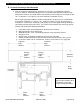
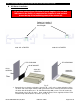
5XPT SLIDING GLASS DOOR INSTALLATION INSTRUCTIONS Section II: General Perimeter Preparation for the Door Frame A. Opening Condition Verification 1. The rough opening should be checked for the correct size as determined by frame size and specified perimeter sealant joint widths listed in the architectural specifications and the shop drawings. (See Fig. A) 2. Establish the face of the Sliding Glass Door line at the head, sill, and jambs.
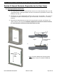
5XPT SLIDING GLASS DOOR INSTALLATION INSTRUCTIONS Section III: Perimeter Accessory Fabrication for Assembled Doors A. Subhead Installation When preparing subframe for anchorage into the building opening, please make note of plumb line alignment of subhead to sill starter possibilities as shown in examples below. Plumb Line 1. Subheads to be field cut to length (cut length = [overall frame dim. + 1/8”], unless shown otherwise) and installed. 2. Make reference to Section I. D.
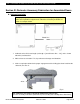
5XPT SLIDING GLASS DOOR INSTALLATION INSTRUCTIONS B. Sill Starter Installation If you have ordered your sill starter in stock lengths, to be cut and fabricated in the field, it is required of the installer to seal and tool across the top of the insulating struts of the starter sill. Sealant by installer if sill starter is ordered stock length 3S91 SILL STARTER 3S90 SILL STARTER FE72 END DAM FE71 END DAM H10F GASKET SLQ9 SCREWS 3S91 SILL STARTER 3S90 SILL STARTER Fig. E 1.
5XPT SLIDING GLASS DOOR INSTALLATION INSTRUCTIONS Groove location in this area where anchor head is shown. Fig. F 2. Fasten down the sill starter with job specified anchors. (See Section I. D.) There is a groove in the sill starter to locate the drill bit. Drill through the sill starter, at the groove, and continue to drill through the support leg underneath the main web of the sill starter. 3S91 sill starter is shown; 3S90 sill starter is similar.
5XPT SLIDING GLASS DOOR INSTALLATION INSTRUCTIONS Section IV: General Installation Without Subhead This section will not be required if the job is being supplied with a subhead. Shim Fig. H Note: Do not drill holes in the door frame head if a subhead is being used. If a subhead is being used, reference Section III, Subsection A, Subhead Installation. (Page 9) 1. Anchorage holes for the head may be drilled prior to setting the door frame in the opening. Note: See Section I. D.
5XPT SLIDING GLASS DOOR INSTALLATION INSTRUCTIONS Section V: Door Frame & Perimeter Sealant Instruction 1. Assemble the door frame and prepare the door frame for installation into the opening. (Page 19 of 34) 2. Seal over the anchor bolt heads. Backbed the Sliding Glass Door to the subhead contact area with silicone sealant before installing the door or cap seal after the door has been installed. (See Fig. D) Silicone backbed or cap seal after the door is installed. EFCO CORPORATION 6/8/2012 PART NO.
5XPT SLIDING GLASS DOOR INSTALLATION INSTRUCTIONS 3. Position the door frame into the opening above the sill starter. Now interlock the door frame sill with the sill starter. Adjust the door, side to side, so as to have an equal caulk width at both jambs. Drive in the continuous arrow shim (WNA3) into cavity between door frame sill and sill starter. Sealant that is required over the arrow shim will be addressed later in these instructions. Preparations for anchorage of the jambs are now ready. (See Fig.
5XPT SLIDING GLASS DOOR INSTALLATION INSTRUCTIONS 5. Anchorage of the jambs will require a tight hole and a clear hole. The clear hole will need to be sized according to the size of the driver and the anchor being used. (See Fig. L) 6. Install blocking and shimming around the Sliding Glass Door frame, at anchor locations, assuring that the door framing is Plumb, Level, and Square. All blocking and shims will be high strength plastic or non-corrosive materials; Not by EFCO. (See Fig. L) 7.
5XPT SLIDING GLASS DOOR INSTALLATION INSTRUCTIONS Note: Ensure that the perimeter shims do not interfere with the exterior and interior perimeter sealant joints that are to be in accordance with the sealant manufacturer’s recommendations. 9. Seal all exposed perimeter joints between structure and door frame perimeters with a skinning, non-hardening type of sealant. Refer to the approved shop drawings for joint design. (See Figs. P and Q) 10.
5XPT SLIDING GLASS DOOR INSTALLATION INSTRUCTIONS Compatible Silicone Sealant Over Arrow Shim by Others. 3S91 SILL STARTER EXTERIOR VIEW Compatible Silicone Sealant by Others INTERIOR VIEW Compatible Silicone Sealant by Others Fig. P Compatible Silicone Sealant Over Arrow Shim by Others.
5XPT SLIDING GLASS DOOR INSTALLATION INSTRUCTIONS Compatible Silicone Sealant by Others EXTERIOR VIEW Fig. Q Compatible Silicone Sealant Over Arrow Shim by Others INTERIOR VIEW Note: All perimeter sealants must be continuous with one another and tooled with no voids. EFCO CORPORATION 6/8/2012 PART NO.
5XPT SLIDING GLASS DOOR INSTALLATION INSTRUCTIONS Section VI: S-5XPT Door Assembly Instructions These recommendations are for general erection procedures only. For actual job conditions, see the details on the shop drawings. For perimeter anchor type and spacing, refer to the approved shop drawings or consult the project design professional. SLQ9 ASSEMBLY SCREWS #10-16 x 1” PH SMS 410 A pt MG 1D04 HEAD 1D25 SILL STT7 OXO MEETING RAIL ATTACHMENT SCREWS #10-12 x 1” PH SMS 18-8 A pt.
5XPT SLIDING GLASS DOOR INSTALLATION INSTRUCTIONS H10B Head Corner Gasket shown H10C Sill Corner Gasket not shown Head (1D04) shown Sill (1D05) not shown EXTERIOR Jamb (1D06) Fig.1 1. Locate frame head (1D04), sill (1D05), and jambs (1D06). Locate head corner gaskets (H10B) and sill corner gaskets (H10C). Locate the SLQ9 (#10-16 x 1” PH-SMS 410 A pt MG) assembly screws. (See Fig. 1) 2. The corner gaskets have a pressure sensitive adhesive on one side.
5XPT SLIDING GLASS DOOR INSTALLATION INSTRUCTIONS 3. Align the screws in the pre-punched holes with the appropriate member (head or sill). Drive the screws through the drilled holes into the screw races. Corner gaskets must be thoroughly compressed for a watertight joint. 4. Anchor the door frame into the opening. Make reference to Sections I & II of this installation instruction. Please make reference to specific details in approved shop drawings that may pertain to your particular job specifications.
5XPT SLIDING GLASS DOOR INSTALLATION INSTRUCTIONS EXTERIOR Fixed Panel Fig.3 9. The fixed panel side rail has an indention mark running vertically along its full length (See Fig. 4). This indention mark, located on the inside, will need to line up with the leading edge of the fixed jamb. Slide the panel and align. This is to allow the fixed panel interlock rail to be in proper alignment with the operable panel meeting rail.
5XPT SLIDING GLASS DOOR INSTALLATION INSTRUCTIONS 10. Once the indention mark is lined up at the jamb, locate 14B1 head spacer. (See Fig. 5) Should the head have a slight dip, the head spacer will lift the head to its proper position. It will also help lock in the upper meeting rail into the head. Take a rubber mallet and drive in the head spacer until the leading edge of the head spacer is flush with the meeting rail. (See Figs.
5XPT SLIDING GLASS DOOR INSTALLATION INSTRUCTIONS 11. The threshold and head filler are now ready for installation. 14N6 Head Filler INTERIOR 14N6 Threshold Fig.7 Square cut the end next to the meeting rail. The head filler and the threshold are the same extrusion. The head filler will be finished to match the door finish. The threshold will be clear anodized with a yellow protective cover.
5XPT SLIDING GLASS DOOR INSTALLATION INSTRUCTIONS Important! Critical Sealant Joints! Use Extreme Care! The following joints are crucial for water performance. 12. For good adhesion, properly clean the metal by following the silicone manufacturer’s recommended cleaning procedures and application. The application of this sealant must be pushed in as the sealant is gunned in, or tooled in a manner that the sealant will make full contact with the joint walls and marry together with adjoining sealant.
5XPT SLIDING GLASS DOOR INSTALLATION INSTRUCTIONS Weather-strip leg All sealant must be continuous with one another and tooled with no voids. THRESHOLD JAMB Fig. 8 Full length sealant across sill SILL See Fig. 8 for Steps A and B below (operable jamb to threshold): Step A. The full length sealant across the sill at the threshold will need to wraparound the weather-strip leg to the jamb. Step B.
5XPT SLIDING GLASS DOOR INSTALLATION INSTRUCTIONS All sealant must be continuous with one another and tooled with no voids. FIXED PANEL MEETING RAIL Full length sealant across sill FIXED PANEL THRESHOLD 2” Fig. 10 SILL See Fig. 10 for Step E below: Step E. Marry a vertical seal to the already applied sealant across the sill; seal the joint between the fixed panel meeting rail and the threshold.
5XPT SLIDING GLASS DOOR INSTALLATION INSTRUCTIONS This page will be required if assembling an OXO door. Otherwise, disregard and proceed to Step 14. Full length sealant across sill OXO FIXED PANEL MEETING RAIL FIXED PANEL THRESHOLD 2” SILL All sealant must be continuous with one another and tooled with no voids. Fig. 11 See Fig. 11 for Step F below: Step F.
5XPT SLIDING GLASS DOOR INSTALLATION INSTRUCTIONS This page will be required if assembling an OXO door. Otherwise, disregard and proceed to Step 14. 13. When assembling an OXO sliding glass door, locate 14E8 meeting rail. Proceed to engage with the fixed panel meeting rail. (See Fig. 12) This should only be done after all panels and thresholds have been sealed in place. Note: 14E8 meeting rail will have a factory fabricated notch, as shown. (See Fig.
5XPT SLIDING GLASS DOOR INSTALLATION INSTRUCTIONS 14. With the sealant all applied, the operable panel is now ready to load with the exception of driving on the sash stop. Before loading the operable panel, the sash stop must be driven into the hollow of the head end of the meeting rail as shown. (See Fig.13) There will be a groove cut in the sash stop. This groove will line up with the outer web of the meeting rail. Fig 13 Fig. 13 15. Locate HNE3 and 18M9 door stop. (See Fig.
5XPT SLIDING GLASS DOOR INSTALLATION INSTRUCTIONS 16. The operable panel will load from the exterior, same as the fixed panel. With the bottom of the operable panel angled outward, tuck into the exterior track of the door frame head. Lift and push the bottom end in and allow the panel’s rollers to rest on the roller track. (See Fig. 15) EXTERIOR Fig. 15 EFCO CORPORATION 6/8/2012 PART NO.
5XPT SLIDING GLASS DOOR INSTALLATION INSTRUCTIONS Adjustment Procedures: 17. Adjustment can now be made to the operable panel. Adjust the rollers so that the operable panel is plumb and true and will roll smoothly. Adjustment is achieved by extending a Phillips driver through the hole, above the slot, in the sill end of the operable panel. Engage the Phillips driver with the roller. Once engaged with the roller, turn clockwise or counterclockwise to adjust the roller up or down. (See Fig.
5XPT SLIDING GLASS DOOR INSTALLATION INSTRUCTIONS Fig.18 14B2 Sill Wind load Adapter 18. With the operable panel or panels open all the way, slide 14B2 sill wind load adapter into the milled slot located in the bottom of the operable panel locking rail. (See Fig. 18) Slide into the milled slot until the back end of the adapter clears the jamb. Push adapter down into the reveal pocket extruded in the sill. The adapter should now slide back and forth in the reveal pocket.
5XPT SLIDING GLASS DOOR INSTALLATION INSTRUCTIONS 19. Screen Installation instruction When hanging the screens, make note that the rollers are at the head. Both the screen head and screen sill will need to engage at the same time. The screen should now roll freely on the track. Locate two (HNE4 or HNE5) anti-lift pieces. Each piece will be attached with two SFZ8 (#8-15 x 1/2” FH SMS 18-8 A pt.) screws. Attach the anti-lift pieces to the existing holes in the screen head.