USER MANUAL GAS PATIO HEATER eiQTTGSS eiQTTGBL STAINLESS STEEL BLACK WARNING: FOR OUTDOOR USE ONLY OR IN WELL VENTILATED AREAS PLEASE KEEP THE MANUAL FOR FUTURE REFERENCE
CONTENTS SAFETY 3 PARTS LIST 5 ASSEMBLY 7 OPERATION 13 LEAK TESTING 14 GAS INFORMATION 14 MAINTENANCE 15 STORAGE 15 TROUBLESHOOTING 16 TECHNICAL SPECIFICATIONS 17 SUPPORT 17 2
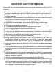
IMPORTANT SAFETY INFORMATION Please read this user manual before using this heater and keep it safe for future reference. ⚫ ⚫ ⚫ ⚫ ⚫ ⚫ ⚫ ⚫ ⚫ ⚫ ⚫ ⚫ ⚫ ⚫ ⚫ ⚫ ⚫ ⚫ ⚫ ⚫ Read the following instructions carefully and be sure your patio heater is properly installed, assembled and cared for. Retain the instructions for future reference. Failure to follow these instructions may result in serious bodily injury and/or property damage.
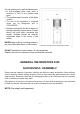
For use outdoors or in well ventilated areas. • A well-ventilated area must have a minimum of 25% of the surface area open. • The surface area is the sum of the walls surface. • The use of this appliance in enclosed areas can be dangerous and is PROHIBITED. • Children and adults should be aware of the high operating temperatures of areas above the post when operating this heater. Children should be carefully supervised when in the vicinity of the heater.
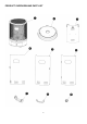
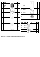
PRODUCT OVERVIEW AND PART LIST 5
# PART NAME PICTURE QTY 1 Burning System Assy 1 2 Base 1 3 4 Heat cover Door 6 Right Side Panel 1 7 Wheels Assembly 1 8 Handle 1 9 Control Dial 1 1 1 PART 5 Left Side Panel PART NAME QTY QTY AA M4 x 10 4 BB M5 x 12 10 CC M6 x 10 2 DD M6 x 20 2 EE M4 4 1 Note: Some of the fittings may be provided pre-attached to the unit.
ASSEMBLY Required Tools: Philips Screwdriver / Adjustable Spanners / Wrenches Leak Detection Solution: One-part detergent and three parts water Before assembly, ensure all packing material and any transit protection is removed.
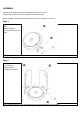
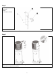
Step 3 Parts required: Door 4 x AA M4x10 Screw 4 x EE M4 Nut Using the M4 Screws and Nuts attach the Dooe by its hinges Step 4 Parts required: Burning System Assembly Control Dial 4 x BB M5x12 Screws Fit the Control Dial into the front of the unit. Screw the Side Panels to the body.
Step 5 Parts required: Heat cover Handle 2 x CC M6x10 Screws Attach the Handle to the heat cover using the M6x10 screws Step 6 Clip the heat cover onto the Burning System Assembly. Use the handle to slide the heat cover around the mesh to block heat from that partciuclar section.
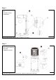
Step 7 When not in use, the heat cover can be clipped lower down the body of the patio heater.
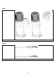
Step 9 Connect the regulator to the gas cylinder (not supplied).
Step 10 Place the gas cylinder inside the Patio Burner. It is now ready to use.
OPERATING INSTRUCTIONS BEFORE FIRST USE AND AFTER EVERY GAS CYLINDER CHANGE, GAS DELIVERY SYSTEM MUST BE PURGED OF AIR BEFORE IGNITING! TO DO THIS, TURN THE CONTROL DIAL ANTI-CLOCKWISE TO THE PILOT SETTING. PRESS THE DIAL IN AND HOLD FOR 1 MINUTE BEFORE ATTEMPTING IGNITION. BATTERY REPLACMENT Remove the control dial. Install 1 AA battery. The negative end of battery goes in first, then replace the control dial. LIGHTING THE PATIO HEATER • Check all connections prior to each use.
LEAK TESTING NEVER USE A NAKED FLAME TO CHECK FOR LEAKS. NEVER LEAK TEST WHILE SMOKING. The gas connections on this appliance are leak tested at the factory prior to shipment. This appliance needs to be periodically checked for leaks and an immediate check is required if the smell of gas is detected. • Make a soap solution using 1 part of liquid washing up liquid to 3 parts water. The soap solution can be applied with a soap bottle, brush, or rag to the leak tested points shown in the figure above.
MAINTENANCE To enjoy years of outstanding performance from your heater, make sure you perform the following maintenance activities on a regular basis: • • • Keep exterior surfaces clean. Use warm soapy water for cleaning. Never use flammable or corrosive cleaning agents. While washing your unit, be sure to keep the area around the burner and pilot assembly dry at all times. If the gas control is exposed to water in any way, DO NOT try to use it. It must be replaced. • Airflow must be unobstructed.
TROUBLESHOOTING PROBLEM Burner won’t light CONDITION FIX Cylinder valve is closed Blockage in orifice or pilot tube Open valve Clean or replace orifice or pilot tube Open gas line and bleed it (pressing control dial in) for not more than 12 minutes or until you smell gas Air in the gas line Low gas pressure Dirt build up around the pilot Connection between the gas valve and pilot assembly is loose Bad thermocouple Gas pressure is low Gas cylinder low or empty Clean dirt from around the pilot Tighten
TECHNICAL SPECIFICATIONS Model: eiQTTGSS eiQTTGBL Nominal Heat input =6.0kW Consumption: 436.3g/h(G30)/428.5g/h(G31) electriQ SUPPORT 0063-20 Country Code BE-CH-CYCZ-ES-FRGB-GR- IEIT-LT-LU-LVPT-SK-SI BG-CY-DKEE-FI-FRHR-HU-ISIT-LT-LUMT-NL-NORO-SE-SISK-TR AT-CH-DESK PL Gas Category I3+(28-30/37) I3B/P(30) I3B/P(50) I3B/P(37) Type of Gas Butane/ Propane Butane/ Propane/ Mixture Butane/ Propane/ Mixture Butane/ Propane/ Mixture Gas pressure 2830/37mbar 20/30mbar 50mbar 37mbar Injector 1.