OWNER‘S MANUAL BEDIENUNGSANLEITUNG MODE D‘EMPLOI
CONTENTS IMPORTANT SAFETY INSTRUCTIONS IMPORTANT SERVICE INSTRUCTIONS DESCRIPTION UNPACKING & WARRANTY INSTALLATION NOTES FRONT VIEW REAR VIEW INPUT A / INPUT B PARALLEL POWER AMP OUTPUT BRIDGED MODE GROUND-LIFT SWITCH MAINS INPUT MAINS OPERATION & RESULTING SPECIFICATIONS / TECHNISCHE DATEN BLOCK DIAGRAM DIMENSIONS / ABMESSUNGEN ....................... 3 ....................... 3 ....................... 4 ....................... 5 ....................... 5 ....................... 6 .......................
IMPORTANT SAFETY INSTRUCTIONS The lightning flash with arrowhead symbol, within an equilateral triangle is intended to alert the user to the presence of uninsulated „dangerous voltage“ within the product’s enclosure that may be of sufficient magnitude to constitute a risk of electric shock to persons. 1. 2. 3. 4. 5. 6. 7. 8. 9. 10. 11. 12. 13. 14. 15. 16.
DESCRIPTION Congratulations! With buying an Electro-Voice CP-Series power amplifier you have chosen a state-ofthe-art appliance that employs most advanced technology. CP-Series power amps combine outstanding audio performance, highest reliability and operational safety. The audio performance of CP-Series power amps are simply extraordinary.
DESCRIPTION UNPACKING & WARRANTY Carefully open the packaging and take out the power amplifier. Next to the power amplifier itself, the package also includes this owner’s manual, a mains cord and the warranty certificate. Keep the original invoice, which states the purchase/delivery date together with the warranty certificate at a safe place.
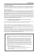
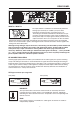
FRONT PANEL Use the POWER switch located on the front panel to power-on the appliance. The soft-start function protects against current inrush peaks on the mains, which in addition prevents the mains line protection switch from activating during power-on. The loudspeaker outputs are activated via relay switching with a delay of approximately 3 seconds to efficiently attenuate eventual power-on noise. The PROTECT LED lights during the delay time and the fans run at maximum speed.
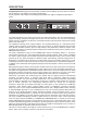
REAR PANEL INPUT A / INPUT B The inputs INPUT A & INPUT B are electronically balanced offering input sensitivity of +5.8dBu (1.51V) for direct connection of mixing consoles, signal processors, etc. The XLR-type connectors OUTPUT A & OUTPUT B are prepared for „through-connecting“ input signals to additional external power amps. The input signal is directly routed to these output connectors. There are no repeaters or other electronic components within that signal path.
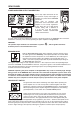
REAR PANEL POWER AMPLIFIER OUTPUT CONNECTORS Power amp output connection for the two channels A (left) and B (right) is provided via professional SPEAKON connectors. These offer an electrical and mechanical secure connection which complies to all security regulations. It also allows the use of high quality speaker cables with a diameter of 4 x 2.5 mm2. The EV accessory assortment includes recommended cables and connectors.
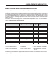
MAINS OPERATION & RESULTING MAINS OPERATION & RESULTING POWER AMP TEMPERATURES The following tables are useful in determining power supply and cabling requirements. The power drawn from the mains network is converted into acoustic output to feed the connected loudspeaker systems plus heat. The difference between drawn power and dispensed power is referred to as leakage power or dissipation (Pd).
BEDIENUNGSANLEITUNG
INHALT WICHTIGE SICHERHEITSHINWEISE WICHTIGE SERVICEHINWEISE BESCHREIBUNG AUSPACKEN & GARANTIE INSTALLATIONSHINWEISE FRONTSEITE RÜCKSEITE INPUT A / INPUT B PARALLEL ENDSTUFENAUSGÄNGE BRIDGED MODE GROUND-LIFT SCHALTER NETZEINGANG NETZBETRIEB & WÄRMEENTWICKLUNG SPECIFICATIONS / TECHNISCHE DATEN BLOCK DIAGRAM DIMENSIONS / ABMESSUNGEN 12 ....................... ....................... ....................... ....................... ....................... ....................... ....................... ......
WICHTIGE SICHERHEITSHINWEISE Das Blitzsymbol innerhalb eines gleichseitigen Dreiecks soll den Anwender auf nicht isolierte Leitungen und Kontakte im Geräteinneren hinweisen, an denen hohe Spannungen anliegen, die im Fall einer Berührung zu lebensgefährlichen Stromschlägen führen können. 1. 2. 3. 4. 5. 6. 7. 8. 9. 10. 11. 12. 13. 14. 15. 16.
BESCHREIBUNG Herzlichen Glückwunsch! Sie haben sich mit einer Endstufe der CP-SERIE von Electro-Voice für ein Gerät modernster Technologie entschieden. Die Endstufen der CP-Serie vereinen überragende Audio-Performance mit höchster Zuverlässigkeit und Betriebssicherheit. Die Übertragungseigenschaften der CP-Endstufen sind hervorragend.
BESCHREIBUNG AUSPACKEN & GARANTIE Öffnen Sie die Verpackung und entnehmen Sie die Endstufe. Zusätzlich zu dieser Bedienungsanleitung liegen dem Gerät ein Netzkabel, und die Garantiekarte bei. Bewahren Sie zur Garantiekarte auch den Kaufbeleg, der den Termin der Übergabe festlegt, auf. INSTALLATIONSHINWEISE Generell sind die Endstufen so aufzustellen oder zu montieren, dass die Luftzufuhr an der Frontseite und die Entlüftung an der Geräterückseite nicht behindert wird.
FRONTSEITE Mit dem POWER Schalter auf der Frontblende wird das Gerät eingeschaltet. Eine Softstart- Schaltung vermeidet dabei Einschaltstromspitzen auf der Netzleitung. Dadurch wird verhindert, dass der Leitungsschutzschalter des Stromnetzes beim Einschalten der Endstufe anspricht. Die Lautsprecher werden über die Ausgangsrelais um ca. 3 Sekunden verzögert zugeschaltet, wodurch etwaige Einschaltgeräusche effektiv unterdrückt werden, die ansonsten in den Lautsprechern hörbar wären.
RÜCKSEITE INPUT A / INPUT B Die Eingänge INPUT A & INPUT B sind elektronisch symmetrisch mit einer Eingangsempfindlichkeit von +5.8dBu (1.51V) für den direkten Betrieb mit Mischpulten, Signalprozessoren usw. ausgelegt. Die XLR-Ausgangsbuchsen OUTPUT A & OUTPUT B sind zum „Durchschleifen“ des Eingangssignals zu weiteren Endstufen vorgesehen. Das Eingangssignal wird dabei direkt auf die Ausgangsbuchsen gelegt, es befinden sich keine Zwischenverstärker oder andere elektronischen Bauteile in diesem Pfad.
RÜCKSEITE ENDSTUFENAUSGANGSBUCHSEN Für die Endstufenkanäle A (Links) und B (Rechts) sind jeweils professionelle SPEAKON Ausgangsbuchsen vorhanden. Diese mechanisch und elektrisch sichere Verbindung wird allen Sicherheitsanforderungen gerecht und erlaubt die Verwendung von Hochleistungslautsprecherkabeln von bis zu 4 x 2,5mm2 Querschnitt. Im Electro-Voice Zubehörprogramm finden Sie Einzelstecker und Kupplungen sowie Hochleistungslautsprecherkabel.
NETZBETRIEB & WÄRMEENTWICKLUNG NETZBETRIEB & WÄRMEENTWICKLUNG IN DER ENDSTUFE Mit Hilfe der folgenden Tabellen können die Anforderungen für Stromversorgung und Zuleitungen bestimmt werden. Die vom Stromnetz aufgenommene Leistung wird in Ausgangsleistung für die Lautsprecher und in Wärme umgewandelt. Die Differenz aus aufgenommener Leistung und abgegebener Leistung nennt man Verlustleistung (Pd). Die durch Verluste entstehende Wärme verbleibt u.U.
MODE D‘EMPLOI
MATIÈRES IMPORTANTES INFORMATIONS DE SÉCURITÉ INSTRUCTIONS DE RÉPARATION IMPORTANTES DESCRIPTION DÉBALLAGE ET GARANTIE REMARQUES SUR L’INSTALLATION FACE AVANT PANNEAU ARRIÈRE INPUT A / INPUT B PARALLEL SORTIE DE AMPLI DE PUISSANCE GROUND-LIFT ENTRÉE SECTEUR SECTEUR ET TEMPÉRATURE RÉSULTANTE SPECIFICATIONS BLOCK DIAGRAM DIMENSIONS 22 ....................... ....................... ....................... ....................... ....................... ....................... ....................... .......
IMPORTANTES INFORMATIONS DE SÉCURITÉ Le symbole «éclair» à l’intérieur d’un triangle signale à l’utilisateur la présence dans l’appareil de câbles et de contacts qui ne sont pas isolés, dans lesquels circule un courant électrique à haute tension, et qu’on ne doit en aucun cas toucher afin d’éviter de recevoir une décharge électrique qui pourrait être mortelle. 1. 2. 3. 4. 5. 6. 7. 8. 9. 10. 11. 12. 13. 14. 15. 16.
DESCRIPTION Félicitations ! En achetant un amplificateur de puissance Electro-Voice de la gamme CP-Series vous avez choisi un appareil haut de gamme employant la technologie la plus avancée qui soit. Les amplis de puissance CP-Series associent des performances audio inégalées, à un fonctionnement fiable et durable. Les performances audio des amplis de puissance CP-Series sont tout simplement extraordinaires.
DESCRIPTION DÉBALLAGE ET GARANTIE Ouvrez avec précautions l’emballage et sortez l’amplificateur de puissance. En plus de l’amplificateur de puissance lui-même, l’emballage contient également le présent mode d’emploi, un cordon secteur ainsi que le certificat de garantie. Conservez en lieu sûr l’original de la facture, qui doit mentionner la date d’achat et de livraison ainsi que le certificat de garantie.
FACE AVANT Utilisez l‘interrupteur POWER situé sur la face avant pour mettre l’appareil sous tension. La fonction de temporisation Soft-Start le protège des sautes de courant, ce qui de plus évite l’activation de la protection interne lors de la mise sous tension. Les sorties haut-parleur sont activées via une commutation par relais avec un délai d’approximativement 3 secondes de manière à atténuer efficacement d’éventuels bruits de commutation.
PANNEAU ARRIÈRE INPUT A / INPUT B Les entrées INPUT A & INPUT B sont symétrisées électroniquement, offrant une sensibilité d‘entrée de +5.8dBu (1.51V) pour le branchement direct de consoles de mixage, processeurs de signal, etc. Les connecteurs de type XLR, OUTPUT A & OUTPUT B, ont été spécialement cablés pour permettre le transit des signaux audio entrant, vers des amplis de puissance externes. Le signal entrant est dirigé directement vers ces connecteurs.
PANNEAU ARRIÈRE CONNECTEURS DE SORTIE DE L‘AMPLIFICATEUR DE PUISSANCE Le branchement de sortie de l‘ampli de puissance pour les deux canaux A (gauche) et B (droit) est établi via des connecteurs professionnels SPEAKON. Ceux-ci offrent une connexion électrique et mécanique fiable satisfaisant à toutes les normes de sécurité. Cette liaison utilise également des câbles de qualité d’un diamètre de 4 x 2,5 mm2.
MAINS OPERATION & RESULTING FONCTIONNEMENT SUR LE SECTEUR ET TEMPÉRATURES RÉSULTANTES Les tableaux suivants vous apporteront une aide précieuse dans la détermination du choix de l’alimentation et des câbles. Le courant secteur est converti en signal de sortie afin d’alimenter les haut-parleurs connectés mais aussi en chaleur. La différence entre le courant utilisé et la puissance restituée est appelée perte de puissance ou dissipation (Pd).
SPECIFICATIONS - Amplifier at rated conditions, both channels driven, 8Ω loads, unless otherwise specified. CP3000S Load Impedance Maximum Midband Output Power THD = 1%, 1kHz, Dual Channel Rated Output Power THD < 0.1%, 20Hz ... 20kHz Max. Single Channel Output Power Dynamic-Headroom, IHF-A Max. Single Channel Output Power Continuous, 1kHz Max. Bridged Output Power THD = 1%, 1kHz Maximum RMS Voltage Swing THD = 1%, 1kHz Power Bandwith THD = 1%, ref.
BLOCK DIAGRAM 31
DIMENSIONS 86,5 380 483 440,5 372 384 88,1 32 5,5
NOTES 33
USA Telex Communications Inc., 12000 Portland Ave. South, Burnsville, MN 55337, Phone: +1 952-884-4051, FAX: +1 952-884-0043 Germany EVI AUDIO GmbH, Hirschberger Ring 45, D 94315, Straubing, Germany Phone: 49 9421-706 0, FAX: 49 9421-706 265 Subject to change without prior notice. Printed in Germany www.electro-voice.