(Model 22-785) (Model 22-785X) Shown with Delta accessory planer stand and roller extension tables PART NO. 909593 - 06-07-05 Copyright © 2005 Delta Machinery To learn more about DELTA MACHINERY visit our website at: www.deltamachinery.com. For Parts, Service, Warranty or other Assistance, please call 1-800-223-7278 (In Canada call 1-800-463-3582).
TABLE OF CONTENTS IMPORTANT SAFETY INSTRUCTIONS . . . . . . . . . . . . . . . . . . . . . . . . . . . . . . . . . . . . . . . . . . . . . . . . . . . . . . . . . . .2 SAFETY GUIDELINES . . . . . . . . . . . . . . . . . . . . . . . . . . . . . . . . . . . . . . . . . . . . . . . . . . . . . . . . . . . . . . . . . . . . . . . .3 GENERAL SAFETY RULES . . . . . . . . . . . . . . . . . . . . . . . . . . . . . . . . . . . . . . . . . . . . . . . . . . . . . . . . . . . . . . . . . . . .
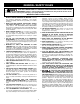
SAFETY GUIDELINES - DEFINITIONS It is important for you to read and understand this manual. The information it contains relates to protecting YOUR SAFETY and PREVENTING PROBLEMS. The symbols below are used to help you recognize this information. Indicates an imminently hazardous situation which, if not avoided, will result in death or serious injury. Indicates a potentially hazardous situation which, if not avoided, could result in death or serious injury.
GENERAL SAFETY RULES READ AND UNDERSTAND ALL WARNINGS AND OPERATING INSTRUCTIONS BEFORE USING THIS EQUIPMENT. Failure to follow all instructions listed below, may result in electric shock, fire, and/or serious personal injury or property damage. IMPORTANT SAFETY INSTRUCTIONS 1. FOR YOUR OWN SAFETY, READ THE INSTRUCTION MANUAL BEFORE OPERATING THE MACHINE. Learning the machine’s application, limitations, and specific hazards will greatly minimize the possibility of accidents and injury. 2.
ADDITIONAL SPECIFIC SAFETY RULES FAILURE TO FOLLOW THESE RULES MAY RESULT IN SERIOUS PERSONAL INJURY. 1. 2. 3. 4. 5. 6. 7. 8. 9. 10. 11. 12. 13. 14. DO NOT OPERATE THIS MACHINE until it is completely assembled and installed according to the instructions. A machine incorrectly assembled can cause serious injury. OBTAIN ADVICE from your supervisor, instructor, or another qualified person if you are not thoroughly familiar with the operation of this machine. Knowledge is safety.
POWER CONNECTIONS A separate electrical circuit should be used for your machines. This circuit should not be less than #12 wire and should be protected with a 20 Amp time lag fuse. If an extension cord is used, use only 3-wire extension cords which have 3-prong grounding type plugs and matching receptacle which will accept the machine’s plug.
EXTENSION CORDS MINIMUM GAUGE EXTENSION CORD RECOMMENDED SIZES FOR USE WITH STATIONARY ELECTRIC MACHINES Use proper extension cords. Make sure your extension cord is in good condition and is a 3-wire extension cord which has a 3-prong grounding type plug and matching receptacle which will accept the machine’s plug. When using an extension cord, be sure to use one heavy enough to carry the current of the machine.
1 2 3 7 4 12 8 10 5 6 11 9 14 15 16 13 Fig.
FOR YOUR OWN SAFETY, DO NOT CONNECT THE MACHINE TO THE POWER SOURCE UNTIL THE MACHINE IS COMPLETELY ASSEMBLED AND YOU READ AND UNDERSTAND THE ENTIRE INSTRUCTION MANUAL. CUTTINGHEAD RAISING AND LOWERING HANDWHEEL B 1. Insert key (A) Fig. 7, into keyway (B) of raising and lowering shaft. A 2. Assemble handwheel (C) Fig. 8, to raising and lowering shaft as shown. Make sure key, which was assembled to shaft in STEP 1, is engaged with keyway in hub of handwheel (C). Fig. 7 3. Assemble decal (D) Fig.
ASSEMBLING TOP COVER AND DUST CHUTE A 1. Fasten the top cover and dust chute (A) Fig. 16, to the top of the planer, as shown, using the three M6x16mm screws (B) supplied. IMPORTANT: The dust chute opening (C) must point to the rear as shown. B B C Fig. 16 2. Fasten the left corner of the cover to the top of the planer using the remaining M6x16mm screw (D) Fig. 17, and cord clamp (E). NOTE: The motor cord (F) must be inserted and positioned into the cord clamp as shown. F E D Fig.
DEPTH OF CUT ADJUSTMENT D The depth of cut on your planer is controlled by raising or lowering the head assembly (A) Fig. 22, which contains the cutterhead and feed rollers. The head assembly (A) moves on four precision ground steel columns, three of which are shown at (B). To adjust for depth of cut, simply loosen the two head assembly lock knobs, one of which is shown at (C), and turn the head raising and lowering handwheel (D).
ANTI-KICKBACK FINGERS WHEN INSPECTING AND CLEANING THE ANTI-KICKBACK FINGERS, MAKE SURE THE MACHINE IS DISCONNECTED FROM THE POWER SOURCE. A series of anti-kickback fingers (A) Fig. 27, are provided on the infeed end of the planer, to prevent kickback of the workpiece during the planing operation. These antikickback fingers operate by gravity and no adjustment is required.
4. Remove the three screws (E) Fig. 34, and remove the chip deflector (F). 5. To check and adjust the knives, proceed as follows: A. Carefully place the knife setting gage (G) Fig. 35, on the cutterhead as shown. B. When the knives are adjusted correctly, the knife (H) Fig. 36, should just contact the bottom of the gage (J), at each end of the gage. Check the remaining two knives in the same manner. D C C.
CONSTRUCTING GAGE BLOCK 1/ " 4 4" In order to check and adjust the height of the chipbreaker, infeed and outfeed roll and adjust the cutterhead parallel to the table, you will need a homemade gage block made of hard wood. This gage block can be constructed by following the dimensions shown in Fig. 38. 2" ADJUSTING HEIGHT OF CHIPBREAKER 1/ " 2 3" 4" Fig. 38 The chipbreaker extends down around the front of the cutterhead and raises as stock is fed through the planer.
ADJUSTING HEIGHT OF INFEED ROLLER The infeed roller is adjusted at the factory at 0.040" below the cutting circle. To check and adjust the height of the infeed roller, proceed as follows: B DISCONNECT MACHINE FROM POWER SOURCE. 1. Make sure the knives are adjusted properly as explained under “CHECKING, ADJUSTING AND REPLACING KNIVES.” A 2. Place the gage block (A) Fig. 42, on the table directly underneath the cutterhead, as shown. Using a 0.
ADJUSTING SPRING TENSION OF INFEED AND OUTFEED ROLLERS A B The infeed and outfeed rollers are those parts of your planer that feed the stock while it is being planed. The feed rollers are under spring tension and this tension must be sufficient to feed the stock uniformly through the planer without slipping but should not be too tight that it causes damage to the board. The tension should also be equal at both ends of each roller.
ADJUSTING CUTTINGHEAD PARALLEL TO TABLE The cuttinghead is set parallel to the table at the factory and no further adjustment should be necessary. If your machine is planing a taper, first check to see if the knives are set properly in the cutterhead. Then check to see if the cuttinghead is set parallel to the table as follows: B A DISCONNECT MACHINE FROM POWER SOURCE. Fig. 49 1. Place gage block (A) Fig. 49, on table directly under front edge of head casting (B) as shown.
MACHINE USE When using your machine, you may want to follow these few simple steps for achieving the best results possible. 1. True Up One Face – Feed one face of the board over a jointer, making thin cuts with each pass, until the entire surface is flat. 2. Plane to Thickness – Place the side you just surfaced in STEP 1 face down and feed the board through the planer, plane until this side is flat.
KEEP MACHINE CLEAN TABLE LUBRICATION Periodically blow out all air passages with dry compressed air. All plastic parts should be cleaned with a soft damp cloth. NEVER use solvents to clean plastic parts. They could possibly dissolve or otherwise damage the material. Apply household floor paste wax to the machine table and extension table or other work surface weekly.
PORTER-CABLE • DELTA SERVICE CENTERS (CENTROS DE SERVICIO DE PORTER-CABLE • DELTA) Parts and Repair Service for Porter-Cable • Delta Machinery are Available at These Locations (Obtenga Refaccion de Partes o Servicio para su Herramienta en los Siguientes Centros de Porter-Cable • Delta) ARIZONA Phoenix 85013-2906 4501 N. 7th Ave.