iNSTALLATiON AND SERVICE MUST BE PERFORMED BY A QUALiFiED iNSTALLER. iMPORTANT: SAVE FOR LOCAL ELECTRICAL iNSPECTOR'S USE. READ AND SAVE THESE iNSTRUCTiONS FOR FUTURE REFERENCE. If the information in this manual is not followed damage, personal injury or death. property exactly, a fire or explosion may result causing FOR YOUR SAFETY: --- Do not store or use gasoline or other flammable appliance.
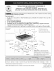
* 30" (76.2 cm) min. for unprotected cabinet and 24" (61 cm) min. for cabinet with protected bottom surface. For Installation with the optional Stainless Steel Backsplash. Gas Cooktop Dimensions 2" (5. I cm) 9" (22.9 cm) Optional Stainless Steel Backsplash C ***Note: Applies only in case of countertop backwall. 4"X 4" (10.2 cm x 10.2 cm) pening to route gas supply. 21/2" 2" (5.1 cm) opening to route power cable. J 7Y4" (18.4 cm) H Gas Cooktop Cutout Dimensions Do not slide unit into cabinet cutout.
Important Notes to the Installer 1. Readallinstructions contained intheseinstallation instructions beforeinstalling thecooktop. 2. Remove allpackingmaterialbeforeconnecting the electrical supplytothecooktop. 3. Observe allgoverning codes andordinances. 4. Besureto leavetheseinstructions withtheconsumer. 5. Note:Foroperation at2000ft. elevations abovesee level,appliance ratingshallbereduced by4 percent foreachadditional 1000ft.
13" (33cm)max.depth , forcabinetinstalled above cooktop 30" (76.2cm)Min. Clearance Between the TopoftheCooking Platform andtheBottom ofanUnprotected Wood or MetalCabinet 24" (61cm)Min. whenBottomofWoodjlf or MetalCabinetis Protected byNotLess ThanI/8" Flame Retardant Millboard "_-. _min cutout and nearest between rearsurface edge of combustible "l_ 18" (45.7 cm) Min. P 30" (76.2 cm) min. clearance between the top of the cooking platform and the bottom of an unprotected wood or metal cabinet.
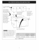
Wall Outlet Location The conversion must be performed by a qualified service technician in accordance with the kit instructions and all _ local codes and requirements. Failure to follow instructions could result in serious injury or property damage. The qualified agency performing this work assumes responsibility for the conversion. 4,, -_ (10.2 cm) Failure to make the appropriate (12.7 cm) Recommended , area for 120V grounded outlet on rear wall.
Thesupplylineshouldbeequippedwithanapproved shutoffvalve.Thisvalveshouldbelocatedinthe same roomasthecooktopandshouldbeina locationthat allowseaseof openingandclosing.Donot blockaccess to theshutoffvalve.Thevalveisfor turningonor shuttingoff gasto theappliance. Grounding Instructions iMPORTANT Please read carefully. For personal grounded.
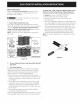
Check Operation Refer to the Use and Care Guide packaged with the cooktop for operating instructions and for care and cleaning of your cooktop. Do not touch the burners. They may be hot enough to cause burns. 1. Burner Bases and Burner Caps This range is equipped with sealed burners as shown (Figure 8). All pieces are at their place. Take note where they are. Remove all packaging material located under the Dual Surface burner head. Make sure the burner is properly aligned and leveled.
5. Adjustthe "LOW"Settingof the DualBurner(see When Figure 8) on the Surface Burner Valve (Figure 10): Note: On the dual valve the low setting of each portion (rear portion of bridge burner and the center portion of bridge burner) should be adjusted individually. a. Push in and turn control to LITE until the rear portion of the bridge burner ignites only. b. Quickly turn knob to LOWEST POSITION. c. If burner goes out, reset control to OFF. d. Remove the surface burner control knob.
LA INSTALACiON Y EL SERVICIO DEBEN SER REALIZADOS POR UN INSTALADOR CAUFICADO. IMPORTANTE: GUARDE ESTAS INSTRUCCIONES PARA USO DEL iNSPECTOR EUeCTRICO LOCAL. LEA Y GUARDE ESTAS INSTRUCCIONES PARA FUTURAS REFERENCIAS F_ Si todas las instrucciones de _ste manual no son observadas a la letra, se puede ocurrir incendios o explosiones que pueden causar da5os materiales, lesiones o la muerte.
* 30" (76.2 cm) rain para un armario protegido. 24" (61 cm) rain para una superficie no protegida. Para ver la InstalaciOn con el Panel Protector Opcional de Acero Inoxidable. Dimensiones de la parrilla de cocinar a gas 2" (5. I cm) Panel Protector Optional de Acero Inoxidable de -9" (22,9 cm) C ***Nota: Se aplica s01o en caso de Panel Protector. Abertura de 4" X 4" para el suministro de gas. Abertura de 2" (5.1cm) de diametro para pasar el cable de alimentaciOn. 7¼" (18.
Notas importantes para el instalador: I. Leatodaslasinstrucciones deinstalaci6n antesde realizar la instalaciOn delaplancha decocinar. 2. Retiretodoslosarticulosdeembalaje antesderealizar lasconexiones el_ctricas a laplancha decocinar. 3.Observe todosloscOdigos o reglamentos estatales 4.Aseg0rese queelconsumidor tengaestasinstrucciones. 5.NOTA:ParalautilizaciOn a masde2 000piesdealtura, lapotencia delaparatodeberaserreducida de4 por cientoacadaI 000piesadicionales.
13" (33cm)max. 30" (76.2cm)rain.de espacio entrelaparte superior delfog6ny la parteinferiordeun armariodemadera o metalsinprotecci6n. 24" (61cm)rain. _j_ cuandolaparteinferior delarmariode maderao metalesta protegida porunaplata cortafuego retardante dellamadenomenos de1/4",cubiertacon unalaminadeacero msgnoinferioralNo. 28,deaceroinoxidable de0.015",aluminiode 0.024"o cobrede 0.020". - _ 7 l _30 " (76 18,, (45_'_7 c!!_ _r_r_c icee_ 0rmllO_tst_bOI e p 0r m)IMinimo de _Pi:ii_i_a r1.
Ubicadon de la toma de corriente Si desea hacer la conversi6n para utilizar el gas propano, use las piezas con orificios fijados provitos en el paquete del manual de instrucciones para la instalaci6n en el paquete escrito "PARA LA CONVERSIONEN GAS PROPANO". de la pared Para hacer la conversi6n del gas natural al gas propano, es necesario utilizar el servicio de un t@cnico calificado, in acuerdo con las instrucciones del fabricante y todos los c6digos y reglamentos reguladores.
Eltubodesuministro degasdebreria incluirunavalvulade cierrecertificada. Esta%lvuladeberiaestarubicada enla mismahabitaci0n delaplancha decocinary deberia estar enunlugarquepermitaunaaberturay cierrefaciles.No bloqueelasentradasdela%lvuladecierre.Lavalvula sirveparaabriro cerrarel pasodelgasalartefacto. Requerimientos el_ctricos: Un circuito derivado conectado correctamente a tierra de 120 voltios, 60 Herz protegido pot un interruptor automatico de 15 amp o un fusible de retardo.
Verifiquela operaci6n Refiera al Manualdel Usuarioquevieneconlaplancha decocinarparalasinstrucciones defuncionamiento yel mantenimiento y lalimpieza desuplancha decocinar. Notoquea losquemadores. Pueden estarsuficientemente calientes parcausar quemaduras. perilla a la POSICIONMAS opuesto alas manecillas del reloj para aumentar el tamaho de la llama. D_ vuelta en sentido a las manecillas del reloj para disminuir la llama.
5.Ajustebajo "LOW"para la v&lvula de quemador de superficie Dual (vea Figura 8 y 10) Nota: En la valvula de quemador triple el ajuste <> de cada portion (portion posterior del quemador puente y la porci6n de centro del quemador del puente) se debe ajustar individualmente. a. Presione y gire el control a la posici6n LITE hasta que la porci6n posterior del quemador puente se encienda. b. Gire r_pidamente a la perilla a la POSICION M4,S BAJA.
UN INSTALLATEUR iMPORTANT: QUALIFIE CONSERVEZ USEZ CES iNSTRUCTiONS DOlT EFFECTUER L'INSTALLATION ET LE SERVICE CES iNSTRUCTiONS POUR LES INSPECTEURS LOCAUX. ET CONSERVEZ-LES POUR RI_FERENCES ULTERIEURES. Si les instructions de ce manuel ne sont pas suivies _ la lettre, il pourrait en r_sulter un incendie ou une explosion susceptible de causer des dornrnages materiels, des blessures ou rn_rne la mort.
Pour I'installation avec le dosseret optionnel en acier inoxydable * Minimum de 30" (76.2 cm) pour armoire non prot6g6e. Minimum de 24" (61 cm) pour surface prot6gee. Dimensions de la plaque de cuisson 30"(76.2 cm) Min.* 2"(5.1 cm) Dosseret optionnel de 9"(22.9cm) en acier inoxydable C ***Note: S'applique seulement dans le cas o0 le comptoir a un rebord sur le tour. Ouverture de 4" X4" (10,2 cm x 10,2 cm) pour Fentree de gaz, 2"(5,1 cm) Dia, ouverture pour F Jecable. 7Y4 (18.4 cm) (2.
Notes importantes La conception de cette plaque de cuisson a _t_ approuv_e par International Approval Services (I.A.S.). II faut prendre certaines precautions d'usage Iors de I'utilisation de tout appareil fonctionnant au gaz naturel ou produisant de la chaleur. Vous trouverez celles-ci dans votre Manuel d'utilisation, lisez-les avec attention. a J'installateur I. Lisez toutes les instructions contenues dans ces instructions d'installation avant d'installer I'appareil. 2.
L'armoire sup6rieure nedoitpas . _ exc_deruneprofondeur de13" (33crn)'_.._; _ D_gagement minimum de30" (76.2 .... rcm)entrelehautdelasurfacede _-_ cuissonetlabasedel'armoireenbois _ ,_ , 2" (5"1cm)estlladistance I minimalerecommand_e __1Degagement minimum entrelerebordarri6rede de30" (76.2cm)entre lehautdelasurface de d6coupage etlemuren cuisson e t labase de materielcombustible leplus I'armoireenboisouen prochedudessus du m6talnonprotegee. comptoir ouenm6talnonprot6g6e.
Conversion au gaz de petrole gaz propane liquefie Utilisez du mastic a joints de 1'6tanch@it_ des raccords de p_trole liqu_fi@. V@rifiez que raccordement, s'il yen a, ne ou Cet appareil fonctionne au gaz naturel ou au gaz propane, estr_gl_enusinepourfonctionneraugaz naturel. Le tuyau d'alimentation doit 6tre @quip_d'un robinet d'arr@t approuv@. Ce robinet devrait 6tre situ_ dans la m6me piece que la plaque de cuisson eta un endroit permettant de I'ouvrir et de le fermer sans difficultY.
Lorsdetouteverificationdepression ducircuita une pressionsup_rieure a Y2 Ib/po2 (3.5 kPa ou 14" C.E.), Installation d_branchez la plaque de cuisson et son robinet d'arr_t individuel de I'alimentation en gaz. Lors de toute v6rification de pression du circuit d'alimentation en gaz a une pression inf6rieure ou 6gale Y2 Ib/po2 (3.5 kPa ou 14" C.E.), isolez la plaque de cuisson du r6seau d'alimentation en gaz en fermant son robinet d'arr6t manuel.
3. V_rifiez les allumeurs II faut v_rifier le fonctionnement 5. R_glez la position LOW des robinets du brQleur de surface double (voir Figure 10): Note: Sur ce type de valve, la position "Low" de chaque portion doit 6tre r_gl_e individuellement. a. Appuyez et toumez le bouton de commande a LITE jusqu'a ce que le brOleur s'allume. b. Toumez rapidement le bouton a la position la plus basse (LOW). c. Si le brOleur s'6teint, remettez le bouton a la position arr_t (OFF). d.
TOP _R GPTI_ ]C_ll1_q INT.ENC. _ CS_EO-=D INTER. ALLL_I. R i [:i,.ff BOJG]E D"._-LL_E-BRdLEL_ LI _viso: ETIGUET_ T0_6 INT, EN_. DE N:_NTE _CF¢_ IN_, _U_t, RICHT FRC_IT D. AV, _ I aKI INT. ENC. D_CG_ECTAq PAR _SrA I1:_1_1_ C_ ENCS_DIDO SL_,:_RIOR EOJGIE D'_J-L_W_-E_LLEL_ DE ENCO_IDO EOJGIE D-_L_EE-B_LLE_ Gj_q, T{_ _ LE_T FRONT I{_. 5g. INT,E_, DE _E IZI_JI_ INTER. _lJ_l. G.AV. INT. ENC. IZ(_JIE_OO _t-RI_R LE_'T _ IGN. SW. INT.E_C._ IZ_J_JIEI_U3 INT{J_./_U_UFI. G./_R.