thermaline S90 ELECTRIC DEEP FAT FRYERS FRITEUSEN ÉLECTRIQUES US FR INSTALLATION- AND OPERATING INSTRUCTIONS INSTRUCTIONS D’INSTALLATION ET D’EMPLOI Doc. 62.9585.01_UL Edition 1 01.
Against wall - contre une paroi Free standing - isolé Connections - Raccordement Electricity - Electricité Fig.1 INSTALLATION DRAWINGS - PLANS D'INSTALLATION Doc. 62.9585.
CONTENTS I. GENERAL INFORMATION ................................................................................................. 3 II. INSTALLATION INSTRUCTIONS....................................................................................... 4 III. OPERATING INSTRUCTIONS............................................................................................ 8 SOMMAIRE IV. INSTRUCTIONS GÉNÉRALES......................................................................................... 11 V.
Page 2 62.9585.
GENERAL INFORMATION I. GENERAL INFORMATION 1. INSTRUCTIONS FOR SAFETY AND USE 1.1 INSTALLATION AND INITIAL OPERATION S The installation, adjustment and initial operation of the appliance must be properly carried out in accordance with the manufacturer's instructions and may only be done by an authorised specialist. S Installations for the supply of electricity must be carried out by qualified installers in accordance with the specific national and local regulations. They bear the responsibility.
INSTALLATION INSTRUCTIONS II . INSTALLATION INSTRUCTIONS 1. INSTALLATION 1.3 ASSEMBLING TWO APPLIANCES The appliance is designed for connection to fixed lines. The appliances are suitable for setting up as single appliances or as a group of appliances. They can be set up freely in the room, side by side, at the side and/or at the back against a wall. Gaps between two appliances or appliance and sidewall should be filled with a FDA approved silicone such as Samco RTV103. (3a) (2) 1.
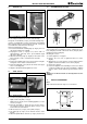
INSTALLATION INSTRUCTIONS 1.4 1.6 SIDEWALL (D) ASSEMBLING ON CASTORS () (5) (4) () (5) (4) 1 1 (3c) 1 a a b Fig.2 Assemblage of sidewall The assembly kit contains two of each of the following: hexagonal screws M8x25 (1 / Fig.1), bolts with retaining rings (2 / Fig.1), mounting links (3 / Fig.1), hexagonal screws M8x16 with serrated washers and hexagonal nuts M8, hexagonal screws M5 with serrated washers (4 / Fig.2) and a fastening angle (5 / Fig.2).
INSTALLATION INSTRUCTIONS 2.1 FRONT PANELS (A) and (B) (1) Fig.6 Front panel D Unscrew screws (1 or 3). Also, in the case of a built-in oven, unscrew screws (2 and/or 4) on the inside of the oven. D Pull the panel away forwards and downwards. 2.2 CONTROL PANEL (C) (2) (3c) (1) 1 a 1 (3c) b (3) Fig. 7 Control panel c D Remove the knob. D Loosen the screws underneath (1 / Fig.7a) and remove the base plate. D Loosen the screws (2 / Fig.7b) and 3 / Fig.7c) D Remove the panel. 2.
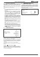
INSTALLATION INSTRUCTIONS 4. ELECTRICAL CONNECTION Each appliance is accompanied by a complete connection and wiring diagram enclosed. This contains full details of the technical specifications (electrical rating, voltage, amperage etc.) Check and ensure that the mains voltage agrees with the voltage given on the specification plate. N.B.: • The corresponding arrangements must be made on-site for the earthing connection and fuse protection for the appliances.
OPERATING INSTRUCTIONS III . OPERATING INSTRUCTIONS 1. GENERAL The appliance is used for deep frying. In operation the basket is suspended. The oil trough temperature is thermostatically controlled according to the preset working temperature. An additional safety thermostat (STB) prevents unacceptably high temperatures from being reached. In the case of appliances with two troughs, these can be used iAccessories supplied: - frying baskets, - basket rest grid, - cover, - outlet pipe.
OPERATING INSTRUCTIONS 4. OIL CARE Filter oil after use: D Turn the mains switch (1) to 0. Wait until the oil has cooled. D Attach the extension piece for draining the oil to the drain cock. D Place the collecting basin with the strainer in it under the drain hole. D Slowly open the drain cock by pushing up the locking device on the lever and simultaneously loosening the drain cock lever by 1/4 turn anti-clockwise. D Drain about 1/3 of the oil through the strainer into the collecting basin.
OPERATING INSTRUCTIONS Page 10 62.9585.
INSTRUCTIONS GÉNÉRALES I. INSTRUCTIONS GÉNÉRALES 1. CONSIGNES DE SÉCURITÉ ET D'UTILISATION 1.1 INSTALLATION ET MISE EN SERVICE S Le montage, le réglage et la première mise en service de l'appareil doivent s'effectuer conformément aux instructions du fabricant et être confiés exclusivement à un technicien agréé. S Le raccordement au réseau électrique doit être réalisé par un installateur agréé, dans le respect des dispositions locales en vigueur dans le pays d'installation.
INSTRUCTIONS RELATIVES À L'INSTALLATION II . INSTRUCTIONS RELATIVES À L'INSTALLATION 1. MISE EN PLACE 1.3 ASSEMBLAGE DE DEUX APPAREILS Cet appareil est conçu pour être raccordé à des conduites fixes. Les appareils peuvent être montés individuellement ou en groupe. Ils peuvent être installés de façon indépendante, côte à côte, avec un côté et/ou la partie arrière de l'appareil reposant contre une paroi.
INSTRUCTIONS RELATIVES À L'INSTALLATION 1.4 PAROI LATERALE (D) 1.6 ASSEMBLAGE SUR ROULETTES () (5) (4) () (5) (4) 1 1 (3c) 1 a a b Fig.2 Montage du paroi latérale Chaque kit d'assemblage comprend respectivement deux vis hexagonales M8 x 25 (1 / Fig.1), des boulons avec circlip (2 / Fig.1), des éclisses (3 / Fig.1), des vis hexagonales M8 x 16 avec rondelles à denture intérieure et des vis hexagonales M8, des vis hexagonales M5 avec rondelles à denture intérieure (4 / Fig.
INSTRUCTIONS RELATIVES À L'INSTALLATION 2.1 PANNEAU AVANT (A) et (B) (1) Fig.6 Panneau avant D Desserrez les vis (1 et 3 Fig.5, Fig.6). Si le four est encastré, desserrez D Extrayez le panneau vers l'avant et le bas. 2.2 PANNEAU DE COMMANDE (C) (2) 1 (3c) (1) a 1 (3c) b (3) Fig.7 Panneau de commande c D Enlever l'interrupteur rotatif. D Dévissez les vis placées au-dessous (1 / fig. 7a) et enlevez la plaque support. D Dévissez les vis (2 / fig. 7b) et 3 / fig.
INSTRUCTIONS RELATIVES À L'INSTALLATION 4. BRANCHEMENT ÉLECTRIQUE Chaque appareil est accompagné d'un schéma complet des connexions et du câblage reprenant les données techniques (puissance électrique, tension, intensité de courant, etc.). Il est nécessaire de contrôler que la tension d'alimentation correspond aux valeurs indiquées sur la plaque signalétique.
INSTRUCTIONS DE FONCTIONNEMENT III . INSTRUCTIONS DE FONCTIONNEMENT 1. GÉNÉRALITÉS L'appareil est employé pour la cuisson à la friteuse. Au cours du fonctionnement, le panier est suspendu. La température du bain d'huile est réglée au moyen du thermostat sur base de la température de travail sélectionnée. Un thermostat de sécurité supplémentaire (STB) empêche que des températures trop élevées soient atteintes. Sur les appareils dotés de deux cuves, celles-ci peuvent être utilisées séparément.
INSTRUCTIONS DE FONCTIONNEMENT 4. TRAITEMENT DE L'HUILE DE FRITURE Filtrez l'huile après chaque utilisation : D Tournez l'interrupteur réseau (1) sur 0. Attendez que l'huile soit refroidie. D Installez la rallonge destinée à effectuer la vidange de l'huile sur le robinet de vidange. D Placez le récipient de recueillement équipé du filtre sous l'ouverture de vidange.