Safety The following information contains important information related to operator safety and may help prevent equipment problems. Make sure you observe all of the precautions listed in this manual. Safety Precautions • Do not modify this product, as a fire, electrical shock, or breakdown could result. • Do not attempt to remove the covers and panels, which have been fixed to the product.
• Do not use this product in an area where ammonia or other gases or chemicals are present. • Do not use this product in an environment with a temperature outside the range specified in the Operator's Manual. • Do not attempt to feed stapled paper, carbon paper or aluminum foil through this product. • Do not touch or scratch the surface of the toner unit developing roller and the PC drum. • Use only the recommended supplies and consumables.
REACH statement Please consult www.kodak.com/go/REACH for information about the presence of substances included on the candidate list according to article 59(1) or Regulation (EC) No. 1907/2006 (REACH). Battery Information This product contains a Lithium Ion button cell battery. This battery can only be removed or replaced by a qualified Service Engineer. Safety Information (34PPM Video Laser Printer) WARNING: This symbol warns against a potential for burns.
All other users WARNING: Use of controls, adjustments of performance or procedures other than those specified in this manual may result in hazardous radiation exposure. This is a semiconductor laser. The maximum power of the laser diode is 15mW, and the wavelength is 770-800 nm. For Denmark ADVARSEL: Usynlig laserstråling ved åbning, når sikkerhedsafbrydere er ude af funktion. Undgå udsttelse for stråling. Klasse 1 laser produkt der opfylder IEC60825 sikkerheds kravene.
Contents 1 Overview . . . . . . . . . . . . . . . . . . . . . . . . . . . . . . . . . . . . . . . . . . . . . . 1-1 Product description . . . . . . . . . . . . . . . . . . . . . . . . . . . . . . . . . . . . . 1-1 Installation . . . . . . . . . . . . . . . . . . . . . . . . . . . . . . . . . . . . . . . . . . . . 1-2 Power source. . . . . . . . . . . . . . . . . . . . . . . . . . . . . . . . . . . . . . . . . . 1-2 Grounding . . . . . . . . . . . . . . . . . . . . . . . . . . . . . . . . . . . . . . . . .
4 Printer Functions . . . . . . . . . . . . . . . . . . . . . . . . . . . . . . . . . . . . . . . 4-1 Printer components . . . . . . . . . . . . . . . . . . . . . . . . . . . . . . . . . . . . 4-1 Paper specifications . . . . . . . . . . . . . . . . . . . . . . . . . . . . . . . . . . . . 4-3 Loading paper into the paper feeding tray . . . . . . . . . . . . . . . . . . . . 4-3 Loading paper in the paper cassette . . . . . . . . . . . . . . . . . . . . . . . . 4-4 Replacing the toner cartridge . . . . . . .
1 Overview This Operator’s Manual provides information and procedures for using the Kodak 3000 DV Plus Digital Scanner. Following is a summary of what is included: Chapter 1, Introduction — provides general information about the Kodak 3000 DV Plus Digital Scanner including a product description, installation information, environmental specifications, an overview of external components, and how to turn the scanner on and off.
Installation Placement of the unit in the environment described below will ensure optimal performance throughout the long life of service for which it was designed. • A well-ventilated place. • An area which is free from ammonia or other organic gases. • A place which has easy access to a power wall socket-outlet so that the unit may be easily plugged in and unplugged. • Any area free from direct sunlight.
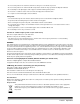
Grounding To prevent electrical shocks caused by electrical leakage, always ground the printer. • Connect the grounding wire to: - the ground terminal of the outlet - a grounding contact that complies with the local electrical standards • NEVER connect the grounding wire to a gas pipe, the grounding wire for a telephone, or a water pipe. Space requirements Scanner The illustration below provides the clearance dimensions.
Operating environment The environmental requirements for operating the system are as follows: Temperature: 10° to 35°C (50 to 95°F) with a maximum fluctuation of 10°C (18°F) per hour. Humidity: System configuration 15 to 85% with a maximum fluctuation of 20% per hour. This scanner is available in the following configurations: Printer mode (connected to the printer) The scanner is connected to a dedicated Kodak 34 ppm Video Laser Printer, allowing scanned images to be printed out directly.
Scanner components Front view 1 2 7 3 4 8 5 6 A-61371 April 2010 1 Screen — the image from the film is displayed for viewing on the screen. The frame on the screen marks the data reading range. 2 Control Panel — most operations are controlled from the keys and indicators on the control panel. See Chapter 2, Control Panel and Functions for more information. 3 Image Rotation Knob — use this knob to rotate the image on the screen.
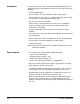
Rear view 12 9 13 14 10 11 1-6 9 Power Switch — used to turn the power to the unit on and off. 10 Connectors — provides connection points for the various options (Film Carrier and Controller). 11 Power Cord Socket — plug the power cord included with the scanner into this socket. 12 Fuse Holder — protects the circuit from overloading. (Ratings: 6A, 250V) 13 Total Counter — shows the total number of prints made regardless of paper size.
Optional accessories Optional accessories are available for the scanner. Contact your Kodak Representative for more information about these accessories. Projection Lenses — several projection lenses are available to change the size and adjust the focus of the image. Four lenses are available: Single lens 7.5X Zoom lens 9-16X Zoom lens 13-27X Zoom lens 20-50X Auto-retrieval Controllers Mini Mars-2 Controller — for automatic reading of 16 mm Cartridge Microfilm using up to 2-level image marks.
Film carriers Fiche Carrier-5 — for use with jackets, microfiche and aperture cards. UC-2 — a motorized carrier for semi-automatic loading of 16 and 35 mm open spool film, microfiche, aperture cards, jackets. UC8 — a motorized carrier for roll films but manual threading. RCF-15A — for automatic loading of 16 mm ANSI Clip Cartridge Microfilm (Open Spool Adapter option). RCF-15M — for automatic loading of 16 mm 3M Type Cartridge Microfilm.
Turning the power on and off To turn the power on: • Press the power switch of the scanner to the (I) On position. • Press the power switch of the printer to the (I) On position. The indicators on the control panel light up and the system starts the initialization operation. When the Wait symbol goes out, the system is ready for printing.
To turn the power off • Press the power switch of the scanner to the O (Off) position. • Press the power switch of the printer to the O (Off) position. Auto Power Save/ Projection lamp functions This system provides two functions that help to decrease power consumption: • The Auto Power Save function that automatically shuts down power to the printer heater. • The Auto Projection Lamp OFF function that automatically turns off the Projection Lamp of the scanner.
2 Control Panel and Functions Following are descriptions of the Control Panel functions. Some functions are available by using the Shift key and some of the functions provide access to optional accessories. This chapter provides an overview of each function and a description of image processing features. Chapter 3, Using the Scanner, provides procedures on how to use each function.
2 Lamp Illuminance — manually adjusts the Projection Lamp illuminance. When the Projection Lamp is Off, it can be turned On again by pressing any key. 3 Film Type — rotates between Auto, Nega, and Posi each time the key is pressed. • 4 5 Auto: the scanner automatically determines between the film type options of negative or positive for print production. • Nega: select when using negative film. Dark and light values of the print will be reversed. • Posi: select when using positive film.
10 Exposure Adjustment — adjusts the density of the image to be printed during the Auto or Manual Exposure mode. • Darker: supports darker image density. • Lighter: supports lighter image density. 11 Multi-Print display — displays the number of prints to be made. Also displays corresponding codes in the event of a malfunction or paper misfeed. The blinking number in this display indicates the print cycle in progress. 12 Multi-Print — used to input the number of prints to be made.
Using the Shift function on Control Panel 1 When you use the Shift function (Clear/Stop key) on Control Panel 1, other options are available.
Control Panel 2 Centering Fit Masking Auto Masking Auto Skew Correction Focus 1 2 3 1 4 5 AF 6 Centering/Fit key — when pressed, enables or disables the Centering and Fit functions. When Auto Masking, Trimming or Masking are set to Off, Auto Masking will automatically be enabled when Centering is selected. • Centering page. : centers all masked images onto the printed • .2 Fit : enlarges the displayed image to fill the page when printed.
3 Auto Masking — turns auto masking on or off. Auto masking omits the frame (non-image area) of a printed film image. Auto masking is only available in the PR mode. • • • 4 The previous Centering/Fit setting is applied when On is selected from the Off state. If Off is selected from the On state, Centering/Fit is disabled. Auto Masking is not applicable with Masking or Trimming. Auto Skew Correction — turns auto skew on or off.
Image processing features This section provides a description of the image processing features. Procedures on how to use these features can be found in Chapter 3, Using the Scanner. Screen image to Print Image Description Auto Masking (1 Frame) The black borders along the edges of the image are masked. Trimming (1 Frame) Everything but the center of the image is masked. Trimming (2 Frames) When 11 x 17” (A3) is selected. The frames surrounding the center of both images are masked.
Screen Image to Print Image Description Page-by-Page Print The system takes two film images that appear side-by-side on the screen and prints them on separate 8 1/2 x 11” (A4) sheets of paper. Auto Paper Select Print The system automatically detects either half-size or full-size film to determine the size of paper for printing (half-size film is printed on 8 1/2 x 11” (A4) portrait paper, full-size film is printing on 11 x 17” (A3) landscape paper.
3 Using the Scanner This chapter provides procedures on how to us the Kodak 3000 DV Plus Digital Scanner. Following is an outline of the basic printing procedure. Detailed procedures on these steps follow in this chapter. 1. Load the film. The procedure for loading film is determined by the type of Film Carrier (optional) that is being used. Review the Operator’s Manual that came with your Film Carrier for more information. 2. Select and replace the lens. 3.
Selecting a projection lens Projection lenses are available in the following types. Select the type of lens that corresponds to the film you are using. 1 Type 1: 7.5X 2 Type 2: 9 to 16X 3 Type 3: 13 to 27X 4 Type 4: 20 to 50X The following list shows the standard types of film and the recommended zoom ratios of lenses to be used with the system printer. The size and format of one frame of film may vary depending on the shooting conditions.
Replacing the projection lens To replace a lens with a magnification different from the pre-installed lens. 1. Grasp the Prism Holder lever and push it up. 2. Pull out the projection lens unit. 3. Slide the desired projection lens unit into the scanner along the lens holder guide. NOTE: When the projection lens unit is slid into position, the scanner automatically selects the optimum screen brightness according to the type of lens being used.
Positioning the film image The size frame markers that correspond to the scanning size are marked on the screen. Through zooming and image rotation, and by operating the film carrier mounted on the system, position the image on the screen so the image fits in the scanning size.
Zooming, focusing and image rotation Zooming in on the displayed image: • Turn the Zooming Ring dial (blue) to bring the image on the screen into the print size frame. Focusing the displayed image: • Center the displayed image and press the AF (Auto Focus) key to let the scanner automatically bring the image into focus. Focus AF NOTE: You can use the Focus (manual focus) keys to manually adjust the focus of the displayed image.
Selecting the film type Auto The system will automatically determine the polarity of the film being used when Auto is selected. NOTE: The system cannot determine the polarity of certain types of film. If the system cannot detect a film type, select it manually. The system does not detect exterior conditions such as when the glass surface of the carrier is dirty or scratched. Nega (Negative film) If negative film is being used, press the Film Type key to select Nega.
Selecting the paper size Press the Paper Selection key to select the desired print size. The system cycles through the available sizes each time you press the key. NOTE: If the printer is not loaded with a desired size paper, load the paper into the printer.
Using the Auto Film Format Selection function When the paper feeding tray and paper cassette is loaded with 8 1/2 x 11” (A4) paper, this function can be used to automatically select the appropriate size of paper for the current print job. 1. Press the Paper Selection key so both the 8 1/2 x 11” (A4) and the 8 1/2 x 11” (A4) LEDs light up. 2. Press the Start key.
Selecting the image density Using Auto Exposure 1. Press the Exposure Mode key to select the Auto Exposure mode. 2. If the Auto Exposure setting is not satisfactory, press the appropriate Exposure Adjustment key, either Lighter or Darker, to set the desired image density. Using Manual Exposure 1. Press the Exposure Mode key and select the Manual Exposure mode. 2. Press the appropriate Exposure Adjustment key, either Lighter or Darker, to set the desired image density.
Entering the number of prints to be made This function is only available in PR mode. Entering a number from 1-9 • Enter the desired number of prints using the Multi Print key “1”. If the 1 key is pressed when 9 is displayed, the number on the display is incremented by one: 10, 11, 12, etc. Entering a number from 10-99 1. Set the tens digit using the 10 key. 2. Set the units digit using the 1 key. For example, to set “25” press the 10 key twice and press the 1 key four times.
Adjusting Image Processing features Using Auto Masking The Auto Masking function prevents the frame (non-image area) of a film image from appearing on the print. • Press the Auto Masking key to turn on this function. Correction NOTES: • The image area of the screen must provide at least 45 mm horizontally and vertically. • The width of the frame to be masked must be at least 10 mm.
Manual Masking panels (option) 1 2 4 3 1 Lengthwise Area Indication panel — use to specify the print area in the vertical direction of the image on the screen. The system makes a print of the image corresponding to the way the Area keys are illuminated. A total of 42 Area keys are placed at 7 mm intervals. 2 Lengthwise Area Clear key — press to clear any print area previously defined in the vertical direction.
Selecting Trimming • Press the Masking key to select Trimming. The lights on the panel light up according to the currently selected paper size and print position. A4 vertical, Center ON ON Example: A4 vertical, Center NOTE: You can print the area specified by the green lights. The lights which do not match with the selected paper size and the print position may light up just after the Job Program is called.
Defining two separate areas • Define the areas to print by specifying the vertical and horizontal areas as follows: 2 end points for vertical and 4 end points for horizontal. 5 6 1 2 3 4 NOTE: The points defining the vertical and horizontal area can be selected in any order. Blinking lights on the indication panels indicate an improper entry of the specified area.
Clearing a defined print area • Press the Vertical and Horizontal Clear keys. Selecting Masking • Press the Masking key to select Masking when you want to mask a specific area of an image. NOTE: The basic operation for Manual Masking is similar to Trimming. Refer to the previous procedures on Trimming and defining areas for Manual Masking procedures.
Centering • Press the Centering/Fit key to turn on Centering. Centering/Fit NOTE: Centering/Fit mode cannot be used if Masking is selected. Fit • Press the Centering/Fit key to turn on Fit. Centering/Fit NOTE: Fit mode cannot be used when the scanner is connected to the PC. Using the Cycle Print mode This function automatically scans the next image following a preset period of time. Images are manually loaded on the carrier glass in between cycles.
Specifying the interval between scanning operations The chart below provides the time intervals that can be set between scanning operations. The time interval is based upon how much time it takes you to move, for example, a roll of film from frame-to-frame. Refer to this table when making a value selection. Value Period (seconds) 1 2 3 4 5 6 7 8 9 0 0.5 1.0 1.5 2.0 2.5 3.0 3.5 4.0 4.5 5.0 1. Press the 10 key to change the value to A. This enables the Cycle Print mode. 2.
Selecting the Resolution 1. Press the Shift key and the Resolution key together. The current resolution is displayed. Resolution 2. Press the Resolution key while holding down the Shift key to set the resolution. Connection mode Resolution Display PR mode 400 dpi 4H 600 dpi 6H 200 dpi 2H 300 dpi 3H 400 dpi 4H 600 dpi 6H 800 dpi 8H PC mode NOTE: 800 dpi can only be selected when the vertical length of the scan image on the screen is less than 220 mm.
Calling the Job Program To call a registered Job Program: 1. Press the Shift key and the Job Recall key together. Job Recall Each time the Job Recall key is pressed while the Shift key is held down, the display is cycled in order of 1J to 2J to 3J. When the desired setting is displayed, release the keys. Using Electronic Zoom In addition to using the lens to zoom, the electrical zoom function has been provided for magnifying the image when it is printed. This function is only available in PR mode.
Skip magnification Hold down the 10 key and the Zoom+ or Zoom- key together, the magnification skips as follows: 10 + Inch Area Metric Area Magnification Size Magnification Size 0.50 minimum 0.50 minimum 0.65 11 x 17” to 8 1/2 x 11” 0.71 A3 to A4 0.77 11 x 17” to 8 1/2 x 11” 0.82 B4 to A4 0.79 8 1/2 x 14” to 8 1/2 x 11” 0.86 A3 to B4 1.00 full 1.00 full 1.27 8 1/2 x 11” to 8 1/2 x 14” 1.15 B4 to A3 1.29 8 1/2 x 11” to 11 x 17” 1.22 A4 to B4 1.
4 Printer Functions This chapter provides information on how to use and maintain your Kodak 34 ppm High Speed Video Laser Printer. Printer components 2 1 4 5 3 6 7 A-61371 April 2010 1 Top cover release lever — used to open the top cover. 2 Output tray extension — fold open when printing on B4 paper larger. 3 Power indicator ⎯ lights when the printer is turned on. 3 Power switch ⎯ use to turn the printer on and off. 4 Paper guides ⎯ slide the guides to secure the paper stack.
8 9 8 Interface connectors ⎯ these two connectors allow the connection with separate scanner units. 9 Power cord socket ⎯ plug the power cord into this socket. 10 11 12 13 9 Top cover ⎯ open to replace the toner cartridge and to clear misfed sheets of paper. 10 Image transfer roller ⎯ transfers the image onto a sheet of paper. Do not touch this roller with your bare hands. 11 Fusing unit ⎯ permanently fixes the image onto the sheet of paper.
Paper specifications Use only the following types of paper: Type — plain and recycled paper (weight 16 to 24 lbs / 60 to 90 g/m2) Standard sizes — 11 x 17”, 8 1/2 x 11”, 8 1/2 x 14”, A3 and A4. Capacity • Paper Feeding Tray: 8 1/2” x 11”, 11” x 8 1/2”, 8 1/2” x 14”, 11” x 17” (or A3, A4) plain and recycled paper - up to 250 sheets. • Paper Cassette: 11” x 8 1/2” 8 1/2” x 14”, 11” x 17” (or A3, A4) plain and recycled paper - up to 500 sheets. Loading paper into the paper feeding tray 1.
4. While pressing the button on the right side of the media guide, slide the media guide to adjust it. NOTE: Make sure the paper fit easily between the guides. Improperly adjusted guides may cause poor print quality, paper jams, or printer damage. Loading paper in the paper cassette 1. Pull out the paper cassette until it stops. 2. While pressing the release buttons (one on each side), remove the paper cassette. 3. Remove the cassette cover.
4. Lift up the gray lever on the right end of the paper retainer, and slide the paper retainer to the right. 5. Lift up on the left end of the paper retainer to remove it. 6. Insert the right end of the paper retainer into the slot for the size of paper to be loaded. NOTE: The paper size detected depending on the position of the paper retainer. Correctly position the paper retainer according to the size of paper to be loaded. 7.
8. Align the four edges of the paper, and then load the paper printing side up. Do not load paper on this side. Long-edge Feed Examples Short-edge Feed Examples Letter, A4 and B5 Ledger, Legal, A3 and B4 NOTE: A maximum of 500 sheets (20 lb. bond [75 g/m2] plain paper) can be loaded. If paper is loaded past the triangular mark, it may not be fed correctly. 9. Press in the button on the paper guide, and then slide the guide against the edge of the paper.
12. When printing on paper B4 or larger, fold open the output tray extension. 13. Affix the paper size labels (supplied with the printer) to the paper cassette in order to indicate the size of loaded paper.
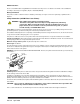
Replacing the toner cartridge 1. Slide the top cover release lever to the right, and open the top cover NOTES: • Never touch the copper or brass electrodes or electrical parts that are located inside the top cover and underneath the toner cartridge, as a printer malfunction can result.
4. Peel off the packing tape. NOTE: Hold the toner cartridge by its handle. Do not open the protective cover of the OPC (the green area) or allow anything to come in contact with the OPC. It is extremely sensitive to hand oils and scratches, both of which reduce print quality. This type of damage is not covered by your warranty. 5. Slowly shake the toner cartridge, tilting it to the left and right 7 or 8 times to distribute the toner. The toner is nontoxic.
6. Align the tabs on the cartridge (one on each side) with the notches in the printer, and then insert the cartridge as far as possible into its compartment 7. Close the top cover, pushing it down until it locks into place. NOTES: • Do not transport the printer with the toner cartridge installed. If toner spills within the printer, decreased print quality may result or the printer may be damaged. • Guidelines are available for disposal of toner cartridges that are replaced during maintenance or service.
Replacing the exhaust filter Replace the exhaust filter on the back of the printer when you replace the toner cartridge. 1. Remove the used exhaust filter and dispose of it according to your local regulations. 2. Remove the new filter from its box and insert it into place. Troubleshooting Misfeed clearing procedure Locate the misfeed using the code and perform the misfeed clearing procedure. CAUTION: The fusing unit inside the printer becomes very hot during operation.
Clearing a misfeed from the paper feeding tray 1. Remove all paper from the paper feeding tray. 2. Pull out the misfed paper. 3. Correctly load the paper into the paper feeding tray. 4. If necessary, open and close the top cover to cancel the misfeed code. Clearing a misfeed from the paper cassette 1. Pull out the paper cassette until it stops. 2. While pressing the release buttons (one on each side) remove the cassette. 3. Pull out the misfed paper.
4. After removing the misfed paper, lower the two levers. 5. Open the paper feed roller cover. 6. Pull out the jammed paper. 7. Close the paper feed roller cover. 8. Align the tabs on the toner cartridge with the notches in the printer and insert the cartridge. NOTE: Do not touch the rollers or gears within the printer. 9. Close the top cover.
Printer maintenance Clean the printer at regular intervals. NOTES: • Use a soft cloth and NEVER use abrasives or corrosive detergents; a damp cloth and a mild home detergent can be used for heavier cleaning. • Never spray cleaning solution directly on the printer’s surface; the spray could penetrate the air vents and damage the printer. • Do not spill water or detergent into the printer.
5 Maintenance This chapter provides maintenance procedures for cleaning the scanner and replacing the projection lamp. Cleaning the scanner The scanner should be cleaned daily for optimal operating conditions. Cleaning the scanner screen • With a damp cloth, clean and remove any dust or debris from the surface of the screen. CAUTION: Never use alcohol or any other solvent when cleaning to avoid causing damage to the screen or erasing the frame size markers.
Carrier Glass (option) NOTE: Before cleaning the carrier glass, remove the projection lens from the scanner. Refer to Chapter 3, “Installing the projection lens” for procedures. • With a damp cloth, clean and remove any dust or debris from the surface of the carrier glass. To open the carrier glass: • Pull the handle of the microfiche holder. With a damp cloth, clean and remove dust and debris by wiping the inner surfaces of the carrier glass.
Replacing the projection lamp Use the following procedure to replace the projection lamp whenever a reduction in brightness on the screen is detected or whenever the lamp burns out. Make sure that the replacement lamp is specified for use with this scanner. If the projection lamp burns out during a print operation, an L2 code appears and the print job will stop (a blank piece of paper may be output depending upon the stage of the job).
5. Insert the new projection lamp so that the mark on its base is facing upwards. Make sure that the new projection lamp is inserted securely so there is no gap between the projection lamp and the lamp socket. Mark CAUTION: Do not touch the reflector mirror surface of the projection lamp. Fingerprints, smudges or debris should be wiped clean with a soft, dry cloth. 6. Insert the projection lamp all the way into the lamp holder of the projection lamp unit. 7.
6 Troubleshooting/Messages This chapter contains information on analyzing and correcting operating problems or errors that may occasionally arise during the use of the Kodak 3000 DV Plus Digital Scanner. Printer /Scanner malfunctions Display Code Description --- E1 Power to the printer is off or there is a problem with the connection of the interface cable to the printer. Turn on the printer or make sure that the interface cable is securely connected.
Call your Kodak Service Representative if one of the following codes is displayed.
Appendix A Specifications The following are specifications for the Kodak 3000 DV Plus Digital Scanner and the Kodak 34 ppm Video Laser Printer. NOTE: Specifications are subject to change without notice. Kodak 3000 DV Plus Digital Scanner Specifications Type Desktop-type microfilm scanner Type of Film Microfiche, Jackets, Aperture Cards, 16 mm & 35 mm Roll Film, 16 mm Film Cartridges Magnification 7.
PR Mode - Kodak 34 ppm Video Laser Printer Specifications A-2 Resolution 600 dpi Output Scale Binary Printing Method Laser Electrostatic Developing System Super Micro-Toning (Super-MT) System Print Size A3, A4 (portrait), A4 (Landscape) 11 x 17”, 11 x 8 1/2”, 8 1/2 x 11”, 8 1/2 x 14” Warm-up Time Less than 70 seconds First Print Time 19 seconds (11 x 17” or A3, 600 dpi, AE) 16.5 seconds (8 1/2 x 11” or A4, 600 dpi, AE) Print Speed 18.
Appendix B User and System Settings This system offers these settings: • User settings that are set up by the user from the control panel. • Settings that are made by the user via User mode. • System settings that are set up by the dealer.
System Setting Fine mode contrast select Auto Skew Correction Retain Machine ID Printing (PR mode only) Cycle Print mode (PR mode only) Paper Size of Paper Feeding tray (PR mode only) Contrast setting Selection Initial Setting Description Contrast Emphasis Outline Emphasis * Applies the following functions as required: Contrast Emphasis: applied when film contains text that is poorly contrasted against its background making it difficult to read.
System Setting Automatic paper source switching Selection Initial Setting Description Auto switching Disable Auto switching * Allows you to specify the paper source when lettersize or A4 paper is loaded in lengthwise or crosswise orientations in the paper feed tray and the paper cassette. Auto switching: printing continues by automatically switching to the remaining paper source after paper in the specified paper source runs out.
Appendix C Key Operator Information When you need to call for service, be prepared to provide the following information: • Your company name, address, telephone number, department name, floor number, machine location, etc. • K# (Mainframe and/or Printer), model name, serial number, condition or system(s) indications(s) on the display, etc. Kodak 3000 DV Plus Digital Scanner Serial Number Model Name K# Kodak 34 ppm Video Laser Printer Serial No. K# Attached Accessories Serial No. Serial No. Serial No.
Appendix D Setting System Default Values Changing settings with the User mode User mode allows the default values of various functions to be set or changed as necessary. Most of these functions are set-up and changed by your Kodak representative, however some User modes can be changed by you. Setting these default values according to your needs saves time and allows you to work more efficiency.
Entering and exiting the User mode 1. Hold down the Shift key and Paper Selection key at the same time for 0.5 seconds. The Multi-Print Display displays a “U”. Paper Selection 11×17 81/2 ×11 81/2 ×11 C Shift User Mode 2. Press the Exposure Adjustment key (Darker or Lighter) to select the specific function. • Pressing the Darker key scrolls through the functions in the following order: U, U1, U2, U3, etc.
Settings in each User mode function U1: Special Print mode — this function is not available. U2: Engineering Enhancement mode — slight image distortion occurring in the scan direction can be corrected with this function. 1. Select U2 in the User mode. 2. Press the Exposure Mode key to display d*. 3. Press the Exposure Adjustment key (Darker or Lighter) to select the desired setting value. 4. Press the Start key to validate the setting.
U4: Paper Feeding Tray Size — the size an direction of the paper loaded in the Paper Feeding Tray can be set with this function. 1. Select U4 in the User mode. 2. Press the Exposure Mode key to display d*. 3. Press the Exposure Adjustment key (Darker or Lighter) to select the desired setting value. 4. Press the Start key to validate the setting. Code Setting Value Initial Setting d0 Letter/A4 (portrait) * d1 Letter/A4 (landscape) d2 Ledger (A3) d3 Legal NOTE: d3 for USA and Canada only.
U6: Year, Month and Date Set mode —the print pattern for the Date Print function can be set with this function. 1. Select U6 in the User mode. 2. Press the Exposure Mode key to display d*. 3. Press the Exposure Adjustment key (Darker or Lighter) to select the desired setting value. 4. Press the Start key to validate the setting. Code Setting Value Initial Setting d0 Year, month, day (2004.05.
3. In each setting mode, press the Multi-Print key to enter the setting value. Each press of the Multi-Press key increases the setting value. When the value exceeds the maximum setting of the selected mode, it returns to 00 or 01 (month, day). 4. When the settings of all modes are complete, press the Start key to valid the time of day setting. U8: Total Scan Counter — the number of scan sequences carried out by the scanner can be displayed with this function. 1. Select U8 in the User mode. 2.