65852 G Instruction Booklet GB IE Gas Hob
Welcome to the world of Electrolux Thank you for choosing a first class product from Electrolux, which hopefully will provide you with lots of pleasure in the future. The Electrolux ambition is to offer a wide variety of quality products that make your life more comfortable. You find some examples on the cover in this manual. Please take a few minutes to study this manual so that you can take advantage of the benefits of your new machine.
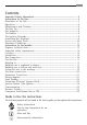
Contents Important Safety Information ..................................................................................... 2 Instructions for the User ............................................................................................... 5 Description of the Hob ............................................................................................................ 5 Operation ...................................................................................................................
Important Safety Information You MUST read these warnings carefully before installing or using the hob. If you need assistance, contact our Customer Care Department on 08705 350350 Installation # # # # # This appliance must be installed and serviced by a competent person as stated in the Gas Safety (Installation and Use) Regulations Current Editions and the IEE Wiring Regulations. For appliances installed in the Republic of Ireland please refer to NSAI-Domestic Gas Installations I.S.
# # # # # # # # # When using the hob for a long period time, the ventilation should be improved, by opening a window or increasing the extractor speed. Do not use this hob if it is in contact with water. Do not operate the hob with wet hands. Ensure the control knobs are in the ‘OFF’ position when not in use. When using other electrical appliances, ensure the cable does not come into contact with the hot surfaces of the cooking appliance.
Description of the Hobs 2 2 3 1 56 78 1. 2. 3. 4. 5. 6. 7. 8. 4 Hob Top Semi-rapid Burner Triple Crown Burner Auxiliary Burner Control knob for front left burner (semi-rapid) Control knob for back left burner (semi-rapid) Control knob for back right burner (triple crown) Control knob for front right burner (auxiliary) INSTALLATION Any gas installation must be carried out by a registered competent person, and in accordance with existing rules and regulations.
Operation Hob burners control knobs The symbols on the knobs mean that : # there is no gas supply there is maximum gas supply there is minimum gas supply Lighting the burners For easier lighting, proceed before putting a pan on the pan support. ! # # # To light a burner: turn the relevant knob anticlockwise to maximum position ( ). Upon ignition, keep the knob pushed down about 5 seconds. This will allow the "thermocouple" (Fig.
Using the hob correctly To ensure maximum burner efficiency, it is strongly recommended that you use only pots and pans with a flat bottom fitting the size of the burner used, so that flame will not spread beyond the bottom of the vessel (see the table beside).
Using the Wok Stand A wok stand is provided to enable you to use a round bottomed wok on the hob. The wok stand must only be used on the triple crown burner, and should not be used with any other type of wok or pan. When fitting the wok stand, ensure the recesses in the frame fit securely onto the bars of the pan supports, as shown in the picture.
Maintenance and Cleaning Before any maintenance or cleaning can be carried out, you must DISCONNECT the hob from the electricity supply. The hob is best cleaned whilst it is still warm, as spillage can be removed more easily than if it is left to cool. This appliance cannot be cleaned with steam or with a steam cleaning machine. The Hob Top Regularly wipe over the hob top using a soft cloth well wrung out in warm water to which a little wasing up liquid has been added.
The Burners The burner caps and crowns can be removed for cleaning. Wash the burners caps and crowns using hot soapy water, and remove marks with a mild paste cleaner. A well moistened soap impregnated steel wool pad can be used with caution, if the marks are particularly difficult to remove. After cleaning, be sure to wipe dry with a soft cloth. The Ignition electrode The electric ignition is obtained through a ceramic electrode and a metal electrode (Fig. 1 - C).
Something Not Working? If the hob is not working correctly, please carry out the following checks before contacting your local Service Force Centre. SYMPTOM % There is no spark when lighting the gas. SOLUTION & & & & % The gas ring burns unevenly. & & Check that the unit is plugged in and the electrical supply is switched on. Check that the RCCB has not tripped (if fitted). Check the mains fuse has not blown. Check the burner cap and crown have been replaced correctly, e.g. after cleaning.
Instructions for the Installer Engineer technical data OVERALL DIMENSIONS Width: 594 mm Depth: 510 mm CUT OUT DIMENSIONS Width: 560 mm Depth: 480 mm SUPPLY CONNECTIONS Gas: R 1/2 inch (1/2 inch male) Rear right hand corner Electric: 230 V~ 50 Hz supply, 3 core flexible cable with non rewireable plug fitted with a 3 amp cartridge fuse. HEAT INPUT Rear Left Burner (semi rapid) Front Left Burner (semi rapid) Rear Right Burner (triple crown) Front Right Burner (auxiliary) 2.
BURNER SEMI-RAPID AUXILIARY TRIPLECROWN POSITION MAX MIN MAX MIN MAX MIN NOMINALTHERMAL POWER kW 2.0 0.45 1.0 0.33 4.0 1.2 NOMINALFLOW RATE m3/h 0.190 0.038 0.095 0.028 0.381 0.114 96 Adjust. 70 Adjust. 146 Adjust. NOMINALTHERMAL POWER kW 2.0 0.45 1.0 0.33 4.0 1.2 NOMINALFLOW RATE g/h 144 29 72 21,5 228 86 71 32 50 28 98 56 TYPE OF GAS NATURAL GAS 20 mbar VALUE = 37.78 MJ/m 3 Ws - 50.7 MJ/ m3 LPG GAS 28-30/37 mbar VALUE = 49.
Important safety requirements This hob must be installed in accordance with the Gas Safety (Installation and Use) Regulations (Current Edition) and the IEE Wiring Regulations (Current Edition). For appliances installed in the Republic of Ireland please refer to NSAI- Domestic Gas Installation I.S. 813 Current Editions and the ETCI Rules for Electrical Installations. Provision for Ventilation Detailed recommendations are contained in the following British Standards Codes Of Practice: B.S. 6172/ B.S.
CLEARANCES REQUIRED WHEN FITTING THE GAS HOB WITH A COOKER HOOD ABOVE CLEARANCES REQUIRED WHEN FITTING THE GAS HOB WITHOUT A COOKER HOOD ABOVE 700 mm 700 mm 400 mm 55 50 m mm m 100 400 mm mm 50 m m FO 0812 FO 0813 Installation IMPORTANT This hob must be installed by a competent person to the relevant Gas Standards. Any gas installation must be carried out by a registered competent person.
FO 0814 FO 0264 A) End of shaft with nut B) Washer C) Elbow On the end of the shaft, which includes the G 1/2" threaded elbow, adjustment is fixed so that the washer is fitted between the components as shown in the diagram. Screw the parts together without using excessive force. Gas Connection Connection to the gas supply should be with either rigid or semi-rigid pipe, i.e. steel or copper. The connection should be suitable for connecting to R 1/2 (1/2 BSP male thread).
Cut Out Size The dimensions of the cut-out are given in the diagram. 51 0 4 59 0 56 48 0 Building In Building over a cupboard or drawer If the hob is to be installed above a cupboard or drawer it will be necessary to fit a heat resistant board below the base of the hob on the underside of the work surface. It is also recommended to carry out the electrical connection to the hob as shown in diagrams 1 and 2.
1 ON/OFF SWITCH 2 ON/OFF SWITCH FLEX OUTLET FLEX OUTLET Building over a kitchen unit with door Proper arrangements must be taken in designing the furniture unit, in order to avoid any contact with the bottom of the hob which can be heated when it is operated. The recommended solution is shown in diagram 3. 3 The panel fitted under the hob ("a") should be easily removable to allow easy access if technical assistance is needed. The space behind the kitchen unit ("b") can be used for connections.
Fitting the Hob into the Worktop Carry out the building in of the hob as follows: 1. place the seals supplied with the hob on the front edge of the cut out. Then, place them at 11 mm from the side edges and at 10 mm from the rear edge, as shown in the diagram, taking care that the seals meet without overlapping. 2. Place the hob in the cut out, taking care that it is centred. 3. Fix the hob with the relevant fixing clamps, supplied with the injectors kit (see diagram).
Electrical connections Any electrical work required to install this hob should be carried out by a qualified electrician or competent person, in accordance with the current regulations. THIS HOB MUST BE EARTHED. The manufacturer declines any liability should these safety measures not be observed. This hob is designed to be connected to a 230 V 50 Hz AC electrical supply. Before switching on, make sure the electricity supply voltage is the same as that indicated on the hob rating plate.
Permanent Connection In the case of a permanent connection, it is necessary that you install a double pole switch between the hob and the electricity supply (mains), with a minimum gap of 3 mm between the switch contacts and of a type suitable for the required load in compliance with the current electric regulations. The switch must not break the yellow and green earth cable at any point. Ensure that the hob supply cord does not come into contact with surfaces with temperatures higher than 50 deg. C.
Fault Finding Preliminary Electrical Systems Check START Isolate appliance and carry out: A: Earth Continuity check. NO YES Green Yellow Carry out: D: Resistance to Earth check. Carry out: C: Polarity check. Electricity supply should now be satisfactory. YES PLUG (with cover removed) Earth Wire Green/Yellow Neutral Wire Blue SOCKET (face view) ( ) E( ) FUSE Inlet wiring faulty. Rectify any fault.
A. EARTH CONTINUITY CHECK Appliance must be electrically disconnected - meter set on W (Ohms) x 1 scale and adjust zero if necessary. — Test leads from any appliance earth point to earth pin on plug. Resistance should be less than 0.1 W (Ohm), check all earth wires for continuity and all contacts clean and tight. B. INSULATION CHECK Appliance electrically disconnected, all switches ON. a) meter set on W (Ohms) x 1 scale. Test leads from L to N in appliance terminal block.
Ignition System / Gas Ignition Ignitor does not spark YES Check gas supply at burner NO Check plug top fuse and replace if necessary Light burner manually Check polarity and earth continuity of supply point Check by pass simmer adjusted Check earth continuity of appliance Check position of the electrode Check fitting of burners Check continuity from 'N' on the mains connector block and "O" on the ignitor unit Check continuity from the tip of each electrode to the terminals 1 to 4 on the ignit
Commissioning When the hob has been fully installed it will be necessary to check the minimum flame setting. To do this, follow the procedure below. the gas tap to the MAX position and ignite. ! 1)2) Turn Set the gas tap to the MIN flame position then turn the control knob from MIN to MAX several times. If the flame is unstable or is extinguished follow the procedure below. Procedure: Re-ignite the burner and set to MIN. ! 1)2) Remove the control knob.
Conversion from Natural Gas to LPG IMPORTANT The replacement/conversion from natural gas to LPG should only be undertaken by a competent person. It is important to note that this model is designed for use with natural gas but can be converted for use with butane or propane gas providing the correct injectors are fitted. The gas rate is adjusted to suit.
Guarantee/Customer Service Standard guarantee conditions We, AEG-Electrolux, undertake that if within 12 months of the date of the purchase this AEG-Electrolux appliance or any part thereof is proved to be defective by reason only of faulty workmanship or materials, we will, at our option repair or replace the same FREE OF CHARGE for labour, materials or carriage on condition that: · The appliance has been correctly installed and used only on the electricity or gas supply stated on the rating plate.
Service and Spare Parts In the event of your appliance requiring service, or if you wish to purchase spare parts, please contact your local Service Force Centre by telephoning 0870 5 929 929 Your telephone call will be automatically routed to the Service Force Centre covering your postcode area. For the address of your local Service Force Centre and further information about Service Force, please visit the website at www.serviceforce.co.
European Guarantee This appliance is guaranteed by Electrolux in each of the countries listed at the back of this user manual, for the period specified in the appliance guarantee or otherwise by law.
35693-3101 07/06 R.0 Subject to change without notice Grafiche MDM - Forlì www.aeg-electrolux.co.