Installation Instructions Remote Blower Assembly for Telescoping Downdraft Ventilation System (1600cfm) 316902918 (April 2012)
Finding Information Table of contents Please read & save this guide Finding Information .................................................2 Important Safety Instructions ..................................3 Shipping Pack.........................................................5 Dimensions .............................................................6 Planning..................................................................7 Installation of Blower Assembly ..............................
Important Safety Instructions What you need to know about safety instructions Warning and Important Instructions appearing in this guide are not meant to cover all possible conditions and situations that may occur. Common sense, caution and care must be exercised when installing, maintaining or operating an appliance. ALWAYS contact your dealer, distributor, service agent or manufacturer about problems or conditions you do not understand.
Important Safety Instructions TO REDUCE THE RISK OF INJURY TO PERSONS IN THE EVENT OF A RANGE TOP GREASE FIRE, OBSERVE THE FOLLOWING*: • SMOTHER FLAMES with a close-fitting lid, cookie sheet, or metal tray, then turn off the burner. BE CAREFUL TO PREVENT BURNS. If the flames do not go out immediately, EVACUATE AND CALL THE FIRE DEPARTMENT. • NEVER PICK UP A FLAMING PAN - You may be burned. • DO NOT USE WATER, including wet dishcloths or towels - a violent steam explosion will result.
Shipping Pack Remote Blower Mounting Hardware Instruction Manual 5
Dimensions Specifications and Dimensions Remote Blower Dimensions 19-3/4" (50.2 cm) Electrical Conduit Connection Main Blower Housing 19-5/8" (49.8 cm) 16-15/16" (43 cm) 2-15/16" (7.5 cm) 9-13/16" (24.9 cm) 10-5/16" (26.2 cm) 8-3/16" (20.8 cm) Air Inlet Duct 10” 6-15/16" (17.6 cm) 12-13/16" (32.5 cm) 30-5/8" (77.8cm) Blower Cover Ø 10" (25.4 cm) 16" (40.6 cm) 30" (76.2 cm) (4) Mount Points 16" (40.6 cm) 1-13/16" (4.6 cm) Discharge Discharge 3-1/4" (8.3 cm) 4” (10.2 cm) 4-3/4” (12.
Planning Installation Planning Ductwork A qualified technician must complete the installation of this appliance. Carefully check the location where the remote blower is to be installed. The remote blower should be placed for convenient access. Make certain that electrical power can be provided in the selected location. Use galvanized or aluminum duct in 8” / 10” round or 3¼”x14” / 4”x14” / 4¾”x14” size, or a combination of both. PVC duct should be used if installing under a poured concrete slab.
Installation of Blower Assembly Remove the Blower Cover Remove the Blower Cover from the Main Blower Housing by removing the (16) silver hex head screws from the Blower Cover. Retain the screws. Remove the Wire box from the Main Blower Housing by removing the 3 hex head screws. Retain the screws. DO NOT attach the Main Blower Housing directly to wall board, ceiling panels, or other non-structural materials.
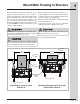
Mount Main Housing to Structure When mounting the Main Blower Housing, the (4) lag bolts must be attached to joists or studs, or other structural members. When mounting the main blower housing between floor joists or walls studs, it is necessary to space the blower housing off the floor or wall using a minimum 2x4 wood spacer. The wood spacers should be properly secured to the joists or studs. DO NOT secure the wood spacers to the sub-floor or wall materials.
Installation on Floor Joists Inlet Metal Duct Discharge Duct Romex or Metal Conduit Floor Joists Main Blower Housing Lag Bolts must be attached to joists, studs or structural members.
Installation on Ceiling Joists 1/4” Lag Bolts (4) Ceiling Joist Discharge Inlet Conduit / Romex Ceiling 11
Installation on Wall Studs Conduit / Romex Inlet 1/4” Lag Bolts (4) Discharge Wall Wall Stud
Installation on Exterior Wall The Outdoor Weather Kit WK-SP360 is required for outdoor installation. Outdoor Weather Kit Exterior Wall WK-SP360 (not included) Sealant Conduit / Romex Blower Cover Zinc Plated Phillips Screws Inlet Wall Stud Discharge 4 3/4" x 14" 1/4” Lag Bolts (4) Note: Minimum 18” from the ground. Sealant Refer to Outdoor Weather Kit Installation Instructions for specific installation details.
Electrical Connections Remote Blower Electrical Connection Loosen the 3 terminal block screws. Insert the leads from the Romex cable into the terminal block and tighten the screws securing the leads in the terminal block. Before making any electrical connections, verify that the blower wheel spins freely. Make the required electrical connections according to the wiring diagram. DOWNDRAFT CONTROL BOX Re-attach the Wire Box using 3 screws.
Verifying Operation and Replacing Cover Verifying Proper Operation After making the required electrical connections, confirm proper operation of the blower. 1. Temporarily re-install the remote blower cover, using 2 screws per side. 2. Turn on the power supply at the circuit breaker. 3. Refer to the Telescoping Down Draft Installation Instructions for additional instructions on proper operation. DO NOT allow any objects to contact any moving parts or electrical connections while verifying blower operation.
Warranty Your appliance is covered by a one year limited warranty. For one year from your original date of purchase, Electrolux will repair or replace any parts of this appliance that prove to be defective in materials or workmanship when such appliance is installed, used, and maintained in accordance with the provided instructions.