Instantaneous Water Heater IH 18 electronic basic IH 21 electronic basic IH 24 electronic basic Instructions for installation and use
Contents Page Important instructions for the user General Operating the appliance Temperature preselection Hot water flowrate Care and maintenance of the appliance 3 3 3 3 4 4 Important instructions for the installer General Appliance constitution Technical data Appliance function Safety temperature limiter Installing the appliance Dimensioned diagram Appliance installation Hood dismounting Wall mounting 5 5 5 6 7 7 8 8 9 9 9 Water connection Concealed installation Installation versions Cleaning the s
Important instructions for the user General - Installation and startup should only ever be performed by an approved installer or authorised installation firm. - Before using the appliance, please read through these instructions carefully. The manufacturer cannot accept any liability for damage resulting from failure to follow these instructions. - Fittings and connecting pipes may get hot. Therefore keep children well away.
Hot water flowrate Up to the appliance’s max. power limit, the instantaneous water heater supplies the set hot water temperature regardless of the water flowrate selected. If the hot water temperature is not attained when the hot water valve is fully opened, more water flows than can be heated by the appliance power. In this case, the hot water tap must be slightly closed. Because of the different inlet temperatures, the hot water output varies depending on the season.
Important instructions for the installer General The instantaneous water heater is manufactured and tested in conformity with the valid IEC specifications and DIN standards. The appliance complies with the Appliance Safety Act. The indications given on the rating plate, the technical connection specifications of the electricity and water companies in the geographical area concerned, and VDE 0100 and DIN 1988 must be observed when the appliance is being installed.
Technical data IH E 18 basis Model Type Nominal capacity 0,4 l mm Weight kg Nominal overpressure Mpa 226 469 99 3,9 I Protection class to VDE IP 25 (splash-water protected) Protection type to VDE See rating plate Test mark G 1/2 A Water connection Electrical connection 3 / PE ~ 380 V 18 kW 21 Spec.
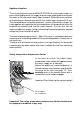
Appliance function The fully electronically controlled ELECTROLUX IH instant water heater is a pressurised appliance for the supply of one or more tapping points and heats the water as the latter continuously flows through it. A flowrate sensor switches on the heating at a flowrate of around 3 l/min and off again at around 2,5 l/min.
Installing the appliance The appliance should only ever be installed or stored in frost-free premises.
Appliance installation Carefully unpack and take out the enclosed pack. Prepare the appliance for assembly. Hood dismounting Press in the engagement lug on the underside of the appliance from above or from the front with a screwdriver and take off the hood. Pull out the connection lead of the temperature set-point pickup on the electronic system. The rotational range of the temperature selector knob can be limited (see page 15).
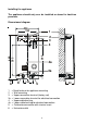
Water connection The water inlet temperature on the cold water connection should be max. 25°C. If plastic pipe systems are used as installation material, the pipe manufacturer must expressly and unreservedly confirm the applicability and quality of his pipes for this application. Concealed installation Insert connector with shutoff spindle (1) in cold water connection and double- nipple (2) in hot water outlet using hemp packing.
Installation versions For fittings directly on the appliance, the bushing openings pre-embossed in the appliance hood must be cut out for the extension pipes of the fitting. The supporting sheet (1) enclosed with the fitting fixes the extension pipes in position and seals the housing openings. To ensure moisture protection, the supporting sheet must be fitted. 2 1 3 4 Fitting must be vertically seated and centrally under the appliance.
Cleaning the strainer insert If the water flowrate is reduced by dirt from the cold water line, the strainerinsert should be cleaned as follows: − Shut off cold water on shutoff unit (1) − Loosen cap nut (2) using a spanner − Take out and clean strainer (3) − Re-assemble in reverse sequence − Open cold water on shutoff unit (1); check tightness 1 3 2 Flow rate limiter 1 2 The flow rate limiter (2) is installed in the cold water connector (1) to allow a constant outlet temperature at high flow pressur
Electrical connection The electrical connection should only ever be made after the water is connected! The appliance is only suitable for a fixed connection of 380 V 3 ~ (three-phase current) . The appliance must be connected to the protective conductor.
Mains connection underneath (alternative) For this connection version, transpose the mains connection terminal 2 (1) from top to bottom. Note the terminal designation on the back wall, and do not cross the connection leads to 3 the safety temperature limiter. Carry out cable inlet opening (2), inlet bush (3), and bush fixing under the mains connection terminal as described above for mains connection. Important! Moisture protection is only guaranteed with the inlet bush fitted in position.
Temperature selector range limitation The maximum temperature able to be set can be limited to 40°C or 45°C. Important! Before dismantling, set the knob to the minimum temperature of 30°C. Detach the temperatur set-point pickup (2) in the appliance hood. Turn the setting dial (3) so that the printed setpoint coincides with the hood mark (1).
Using the appliance for the first time and checking The unit must be installed and started up by an approved firm of installers which accepts liability for safety and proper function. Before the appliance is energised (connected to the electricity supply), it should be thoroughly flushed with cold water and the tightness of the screwed joints checked.
Fault-finding (important instructions for the trained engineer) In the event of any fault, a check should first be made to ascertain whether the fuse and line protection switch have tripped.
Fault indications Fault pattern 1 Idicator LED 1 Possible faults LED 2 No display Appliance does not work - Flowrate sensor not plugged / defective - L1 or L3 phase missing No display Setpoint temperature not reachd 2 3 4 5 - L2 phase missing FLASHES FLASHES long long Constant warm water temp.
Important for the expert The electronic controls the safety-function of the appliance. When a fault is noticed, the fault indicator (LED) blinks and the heating element is switched off. After the fault has been recitified, fault memory will be automatically cancelled Instructions for the fault finding see in "Instructions for installation and use" page 17and 18.
Customer service If your appliance has a fault, please contact your customer service centre for advice. Electric appliances should only ever be repaired by a trained electrician, since the user may be seriously endangered by improper repairs. A list of the addresses of customer service centres is attached. If your appliance requires service, you will need to quote these numbers indicated on the rating plate. Serial No. To save enquiries, copy the data from the rating plate and keep them handy.