......................................................... .........................................................
Congratulations Table of Contents Congratulations and thank you for choosing Electrolux split-type air conditioner. We are sure \RX ZLOO ¿QG \RXU QHZ DLU FRQGLWLRQHU D SOHDVXUH WR use. Congratulations ......................................... 1 Before you use the air conditioner, we recommend that you read through the entire user manual, which provides the description of the air conditioner and its functions.
Safety precautions Please ready this installation manual and the user manual before installation and carefully store in a handy place for later reference. ,QVLGH WKLV PDQXDO \RX ZLOO ¿QG PDQ\ KHOSIXO KLQWV on how to use and maintain your air conditioner properly. Electrical work must be installed by a licensed electrician. Be sure to use the correct rating of the power plug and main circuit for the model to be installed.
Before Installation Tools Needs for Installation 1 2 3 6 7 8 9 Level gauge Screw driver Electric drill Hole core drill ( PP 70mm) Flaring tool set 6SHFL¿HG WRUTXH ZUHQFKHV Spanner (half union) A glass of water +H[DJRQDO ZUHQFK PP 10 Gas-leak detector 11 Vacuum pump 12 Gauge manifold 13 Users manual Thermometer Multimeter 16 Pipe cutter 17 Measuring tape Items Required for Installion Number Name of Accessories Indoor unit mounting plate Clip anchor Quantity 1 Not supplied 6HOI WD
Space to the ceiling FP DERYH Product Description Indoor Unit Space to the wall FP DERYH Space to the wall 3m a bove 2m above FP DERYH Air outlet side 6SDFH WR WKH ÀRRU FP DERYH Space to obstruction Air inlet side Space to the wall 30cm above cm 30 e ov ab FP DERYH e ov ab Space to the wall 2m Air outlet side Outdoor Unit
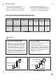
7 Select place about 1m or more away from a TV set or any other electric appliance. Installation Site Instruction A proper installation site is vital for correct and HI¿FLHQW RSHUDWLRQ RI WKH XQLW Avoid the following sites where: VWURQJ KHDW VRXUFHV YDSRXU ÀDPPDEOH JDV or volatile liquids are emitted. high-frequency electro-magnetic waves are generated by radio equipment, welders or medical equipment. salt-laden air prevails (such as close to coastal areas).
Rooftop Installation 1 If the outdoor unit is installed on a roof structure, be sure to level the unit. 2 Ens ure the roof structure and anchoring method are adequate for the unit location. 3 If the outdoor unit is installed on roof structures or external walls, this may result in excessive noise and vibration, and may also be classed as non-serviceable installation.
Step 2: Outdoor Condensate Drainage (only for heat pump model) Outdoor Unit Installation Step 1: Securing of Outdoor Unit $QFKRU WKH RXWGRRU XQLW E\ ¿[LQJ WKH KROHV H[LVWHQW LQ LWV EDVHG ZLWK EROWV DQG QXWV RI 10 mm tightly (not included). Place the outdoor unit over a horizontal concrete or rigid surface (never directly over grass or land). During heating operation, the condensate and defrosting water should be drained out reliably through the drain hose.
Installation Step 1: Installation of Mounting Plate 1 Fit the mounting plate horizontally on the wall ZLWK ¿YH RU PRUH VHOI WDSSLQJ VFUHZV W\SH 67 [ LWHP RQ SDJH 2 Be sure that the mounting plate has been ¿[HG ¿UPO\ HQRXJK WR ZLWKVWDQG DERXW NJ Meanwhile, the weight should be evenly shared by every screw. 3 If the wall is made of brick, concrete or the like, GULOO ¿YH RU VL[ KROHV RI PP GLDPHWHU LQ the wall. Insert clip anchor (item 2 on page 3) for appropriate mounting screws.
Mounting Plate Type C Step 2: Drill Piping Hole 1 Determine hole positions according to the GLDJUDP 'ULOO RQH KROH Ɏ RU Ɏ PP in the wall at a slight downward slant to the outdoor side. Piping hole Model Ɏ PP &RROLQJ FDSDFLW\ : &RROLQJ FDSDFLW\ ! : Ɏ PP 2 7KH LQFOLQDWLRQ PXVW EH EHWZHHQ PP LQ order to ensure a good drain of condensed water generated by the indoor unit.
3 Wrap the insulating pipe with wide vinyl tape to prevent the shift of insulating pipe. Slant the drain hose downward slightly for smooth drainage of condensing water. The piping can be output from right, rear right, left or rear left. 1 When routing the piping and wiring from the left or right side of indoor unit, cut off the tailings IURP WKH FKDVVLV ZKHQ QHFHVVDU\ VHH ¿JXUH below).
Piping on the rear right side Follow the instruction as below for exchanging the position of drain cap and drain hose in case from left side to right. (a) Pull out the drain cap at the rear right of the indoor unit. Drain cap (b) Pull out the drain hose at the rear left of the indoor unit. Drain hose from the right side Piping on the right side Drain hose Drain hose from the left side (c) Put the drain cap into the drain hole at the rear left of the indoor unit.
Do not route both refrigerant piping and drain hose from the right side to the left side to prevent big gap between the indoor unit and the wall. Turn lightly the cable to make the connection easier later. Be careful not to let the drain hose become slack. Heat insulate the connecting pipe. Be sure that the drain hose is located at the lowest side of the buddle.
Step 5: Installation of Connection Pipe Flare nut Refrigerant pipe connection Copper tube 1 Flaring work Main cause for refrigerant leakage is due to GHIHFWV LQ WKH ÀDULQJ ZRUN &DUU\ RXW FRUUHFW ÀDULQJ work using the following procedure: caution A: Cut the pipes and the cable. Use the piping kit accessory (if applicable) or pipes purchased locally. ,W LV QRW SRVVLEOH WR SXW WKHP RQ DIWHU ÀDULQJ ZRUN Measure the distance between the indoor and the outdoor unit.
Step 6: Piping Connection - Indoor Unit A: Connecting the indoor unit tubing to the connection piping: $OLJQ WKH FHQWHUV RI WKH SLSHV DQG VXI¿FLHQWO\ WLJKWHQ WKH ÀDUH QXW ZLWK \RXU KDQGV ¿UVW B: Wrap the insulation material around the connecting portion: Cover the indoor unit pipe and the connection pipe with the heat insulation material. Bind them together with vinyl tape so that there is no gap.
Pipe Drain hose Vinyl tape (narrow) Connection power cable Step 7: Piping Connection Outdoor Unit A: $OLJQ WKH FHQWHUV RI WKH SLSHV DQG VXI¿FLHQWO\ WLJKWHQ WKH ÀDUH QXW ZLWK \RXU KDQGV Wrap with vinyl tape (wide) C: Positioning the indoor unit: Remove the spacer. Hook the indoor unit onto the upper portion of the mounting plate (Engage the hooks of the mounting plate into the openings at the rear top of the indoor unit).
B. In cases where the outdoor unit is installed below the indoor unit level: Wrap the piping, drain hose and connecting cable from the down to up. Secure the wrapped piping along the exterior wall using saddle or equivalent. Seal small openings around piping with a gum type sealer.
2 The yellow-green wire in air conditioner is the earthing wire which can not be used for other purposes. Improper earthing may cause electric shock. 3 The earth resistance should accord to the national wiring regulation. 7KH XVHU¶V SRZHU PXVW KDYH UHOLDEOH HDUWKLQJ terminal. Do not connect the earthing wire with the following: Wrap wires that are not connected with insulating tape so that they do not touch any electrical or metal parts. 6HFXUH WKH ZLUHV ¿UPO\ ZLWK WKH FDEOH clamp.
2 Take off wire cable clamp. Connect and screw the power connection cable onto the terminal EORFN IROORZLQJ FRUUHVSRQGLQJ LGHQWL¿FDWLRQ numbers and colors on the terminal blocks of indoor and outdoor units. Blue Black Brown Earthing wire (Yellow-Green) caution The following may be caused by voltage drop: Vibration of a contactor, which will damage the contact point, fuse blowing, disturbance of the normal function of the overload.
Therefore, the indoor unit and tubing between the indoor and outdoor units must be tested for leakage and evacuated to remove any noncondensables and moisture from the system. Air Purging With Vacuum Pump Preparation Drian hose Check that each tube (both liquid and gas side tubes) between the indoor and outdoor units have been properly connected and all wiring for the test has been completed. Remove the service valve caps from both gas and liquid sides on the outdoor unit.
When Using the Vacuum Pump Refrigerant Outdoor Unit Lo stop valve (3-way valve) Indoor Unit Gas side Liquid side Half union Hi stop valve (2-way valve) 1 &RPSOHWHO\ WLJKWHQ WKH ÀDUH QXWV RQ $ % & and D, connect the manifold valve charge hose (blue) to the charge port of the low pressure valve (3-way valve) on the gas pipe side. 2 Connect the other charge hose (yellow) of manifold to the vacuum pump. 3 Fully open the handle Lo of the manifold valve.
Operation Test Test and Running 1 Before Operation Test Gas Leakage Check Do not switch on power before installation is ¿QLVKHG FRPSOHWHO\ 1 Soap water method: Apply soap water or liquid neutral detergent on all valves and pipe connections (A, B, C and D, UHIHU WR WKH ¿JXUH EHORZ LQYROYHG LQ LQVWDOODWLRQ by a soft brush to check for leakage. If bubbles come out, the pipes have leakage.
Pump Done When relocating or disposing of the air conditioner, pump down the system following the procedure below so that no refrigerant is released into the atmosphere. Connect the hose of manifold valve to the charge port of stop valve on the gas pipe side of the outdoor unit. Check After Installation Items to be checked Possible malfunction +DV WKH XQLW EHHQ ¿[HG ¿UPO\" The unit may drop, shake or emit noise.
Félicitations Sommaire Nous vous félicitons et vous remercions d’avoir choisi un climatiseur de type split Electrolux. Nous sommes persuadés que vous aurez plaisir à utiliser votre nouveau climatiseur. Félicitations ................................................ 23 Avant d’utiliser le climatiseur, nous vous recommandons de lire attentivement l’ensemble de la présente notice, où vous trouverez la description de l’appareil et de ses fonctions.
Consignes de sécurité Préparez soigneusement ce manuel d’installation ainsi que la notice d’utilisation avant d’installer l’appareil et conservez-les dans un endroit facile G¶DFFqV SRXU WRXWH FRQVXOWDWLRQ XOWpULHXUH Notice d’installation attention Dans ce manuel, vous trouverez de nombreux conseils sur la façon d’utiliser et d’entretenir votre climatiseur. 1.
Avant l’installation Outils nécessaires pour l’installation 1. 2. 3. 4. 5. 6. 7. 8. 9. 10. Détecteur de fuites de gaz 11. Pompe à vide Jauge de niveau Tournevis Perceuse électrique Foreuse ( 55 mm / 70 mm) &RIIUHW GXGJHRQQLqUH &OpV G\QDPRPpWULTXHV VSpFL¿pHV Clé à molette (demi raccord) Un verre d’eau Clé hexagonale (4 mm) 12. Jauge de réfrigération 13. Notice d’utilisation 14. 7KHUPRPqWUH 15. 0XOWLPqWUH 16. Coupe-tube 17.
Espacement avec le plafond Espacement avec le mur 15 cm ou plus Espacement avec le mur 15 cm ou plus 2 m ou plus 3mo u plu s Côté du tuyau de sortie d’air Espacement avec le sol Espacement avec un obstacle 50 cm ou plus Élément intérieur 15 cm ou plus Description de l’appareil Côté du tuyau d’entrée d’air Espacement avec le mur 30 cm ou plus 30 2 m ou us pl cm ou us pl 50 cm ou plus Espacement avec le mur Côté du tuyau de sortie d’air Élément extérieur 26
Instructions pour l’emplacement d’installation Choisir le bon emplacement pour l’installation est SULPRUGLDO SRXU XQ IRQFWLRQQHPHQW FRUUHFW HW HI¿FDFH de l’appareil. Évitez les emplacements suivants : à proximité d’émissions de forte chaleur, de vapeur, GH JD] LQÀDPPDEOHV RX GH OLTXLGHV YRODWLOV d’ondes électromagnétiques à hautes fréquences émises par des matériels radio ou des équipements de soudure ou médicaux. où l’air est chargé en iode (par exemple à proximité des côtes).
Installation sur le toit 1. Si l’élément intérieur est installé sur un toit, veillez à l’installer de niveau. 2. Assurez-vous que la structure du toit et la méthode d’ancrage sont adaptées à l’emplacement de l’appareil. 3. Si l’élément extérieur est installé sur un toit ou sur un mur extérieur, il pourrait émettre des bruits et vibrations excessives et pourrait également être classé comme installation non utilisable.
Étape 2 : Vidange par condensation extérieure (uniquement pour les modèles avec pompe à chaleur) Étape 1 : Stabilisation de l’élément extérieur Installation de l’élément extérieur $QFUH] O¶pOpPHQW H[WpULHXU HQ ¿[DQW OHV WURXV existants dans la base avec 4 boulons et écrous de 10 mm (non inclus) et en les serrant bien. Placez l’élément extérieur sur une surface horizontale en béton ou rigide (jamais directement sur l’herbe ou dans la terre).
Installation Étape 1 : Installation de la plaque de montage 1. Installez la plaque de montage en position horizontale sur le mur à l’aide de 5 vis auto-taraudeuses ou plus (type ST4 x 25, élément 3 à la page 3). Installez la plaque de montage et percez des trous dans le mur selon la structure du mur et selon les points de montage se trouvant sur la plaque. (les dimensions sont indiquées en mm sauf indication contraire) 2.
Type de plaque de montage C Gauche Droite Étape 2 : Perçage de trous de tuyauterie 1. Déterminez la position des trous selon le GLDJUDPPH 3HUFH] WURX Ɏ RX Ɏ PP GDQV OH PXU HQ O¶RULHQWDQW OpJqUHPHQW YHUV OH bas du côté extérieur. Trou de tuyauterie Modèle Ɏ 55 mm Capacité de refroidissement <4 500 W Ɏ 70 mm Capacité de refroidissement >4 500 W 2. /¶LQFOLQDLVRQ GRLW rWUH GH j PP D¿Q d’assurer une bonne évacuation de l’eau condensée générée par l’élément intérieur.
3. Enveloppez le tuyau isolant avec un large ruban vinyle pour éviter que le tuyau ne se déplace. 3HQFKH] OpJqUHPHQW OH WX\DX GH YLGDQJH YHUV le bas pour que l’eau de condensation s’écoule doucement. /D WX\DXWHULH SHXW rWUH VRUWLH SDU OD GURLWH O¶DUULqUH GURLW j JDXFKH RX O¶DUULqUH JDXFKH 1. Lorsque vous dirigez la tuyauterie et le câblage vers le côté droit ou gauche de l’élément intérieur, détachez les caches du châssis si besoin est (voir illustration ci-dessous).
7X\DXWHULH j O¶DUULqUH GX F{Wp GURLW Suivez les instructions décrites ci-dessous pour changer la position du bouchon et du tuyau de vidange de la gauche vers la droite. D 6RUWH] OH ERXFKRQ GH YLGDQJH j O¶DUULqUH GH l’élément intérieur, du côté droit. Bouchon de vidange E 6RUWH] OH ERXFKRQ GH YLGDQJH j O¶DUULqUH GH l’élément intérieur, du côté gauche.
Ne dirigez pas le tuyau du réfrigérant et le tuyau de vidange tous les deux du côté droit vers le côté gauche pour éviter qu’un grand espace ne se forme entre l’élément intérieur et le mur. 7RXUQH] OpJqUHPHQW OH FkEOH SRXU TXH OH raccordement soit plus facile ultérieurement. Veillez à ne pas laisser le tuyau de vidange détendu. Isolez le tuyau de raccordement de la chaleur. Assurez-vous que le tuyau de vidange se trouve du côté le plus bas de l’ensemble.
Étape 5 : Installation du tuyau de raccordement Raccordement du tuyau réfrigérant Écrou évasé Tuyau en cuivre 1 Travail d’évasage La cause principale des fuites de réfrigérant est due à des défauts dans le travail d’évasage. Effectuez un travail d’évasage approprié en utilisant la procédure suivante : attention A : Coupez les tuyaux et le câble. Utilisez les accessoires du kit de tuyauterie (si disponible) ou des tuyaux achetés localement.
Étape 6 : Raccordement de tuyauterie élément intérieur A : Raccordement des tuyauteries des éléments intérieur et extérieur : Alignez le centre des tuyaux et serrez d’abord l’écrou évasé autant que possible à la main. B : Enveloppez l’isolant autour de la partie du raccordement : Couvrez le tuyau de l’élément intérieur et le tuyau de raccordement avec un isolant thermique.
Tuyau Tuyau de vidange Ruban vinyle ¿Q Câble de raccordement électrique Étape 7 : Raccordement de tuyauterie élément extérieur A : Alignez le centre des tuyaux et serrez l’écrou évasé autant que possible à la main. Enveloppez de ruban vinyle (large) C : Positionnement de l’élément intérieur : Retirez l’entretoise.
B. Si l’élément extérieur est installé endessous du niveau de l’élément intérieur : Étape 9 : Installation électrique Enveloppez la conduite, le tuyau de vidange et le câble de raccordement du bas vers le haut. Consignes de sécurité Attachez la tuyauterie enveloppée le long du mur extérieur en utilisant un collier ou équivalent. Consignes de sécurité électrique avant de commencer l’installation : Bouchez les petites ouvertures autour de la tuyauterie avec un mastic de type gomme.
/H ¿O MDXQH YHUW GX FOLPDWLVHXU HVW OH ¿O GH WHUUH HW QH peut pas être utilisé pour d’autres buts. Un mauvais raccordement à la terre peut causer un choc électrique. 4. (QYHORSSH] OHV ¿OV TXL QH VRQW SDV EUDQFKpV DYHF GX UXEDQ LVRODQW D¿Q TX¶LOV QH WRXFKHQW aucune partie électrique ou métallique. 3 La résistance de terre doit correspondre aux réglementations nationales de câblage. 6. Remettez le couvercle du câblage en place et vissez-le.
2. 5HWLUH] OH VHUUH ¿OV %UDQFKH] HW YLVVH] OH FkEOH de raccordement électrique sur le bornier en VXLYDQW OHV QXPpURV HW OHV FRXOHXUV G¶LGHQWL¿FDWLRQ correspondants sur les borniers des éléments intérieur et extérieur. Bleu Noir Marron Fil de terre (jaune-vert) attention Les situations suivantes peuvent causer une perte de tension : Les vibrations d’un contacteur, qui endommageront le point de contact, un fusible grillé, des perturbations de la fonction normale de la surcharge.
L’élément intérieur et la tuyauterie entre les éléments intérieur et extérieur doivent être testées à la recherche de fuites et vidangés pour retirer toute O¶KXPLGLWp GX V\VWqPH Purge d’air avec la pompe à vide Préparation Tuyau de vidange 9pUL¿H] TXH FKDTXH WX\DX OHV WX\DX[ GH liquide et de gaz) entre les éléments intérieur et extérieur ont été correctement raccordés et que les câblages pour le test ont été effectués.
Lorsque vous utilisez la pompe à vide Fluide frigorigène Vanne d’arrêt basse (soupape à 3 voies) Élément extérieur Élément intérieur Côté gaz Côté liquide 1. 6HUUH] HQWLqUHPHQW OHV pFURXV pYDVpV VXU $ % & HW D, raccordez le tuyau de charge de la soupape (bleu) au port de charge de la soupape de basse pression (soupape à 3 voies) du côté du tuyau de gaz. 2. Raccordez l’autre tuyau de charge (jaune) de la soupape à la pompe à vide. Vanne d’arrêt haute (valve à 2 voies) Demiraccord 3.
Mode test Test et fonctionnement 1. Avant le mode test Test de fuites de gaz Ne branchez pas l’appareil tant que l’installation Q¶HVW SDV HQWLqUHPHQW WHUPLQpH 1.
Pompage Lorsque vous déplacez ou jetez le climatiseur, SRPSH] OH V\VWqPH HQ VXLYDQW OD SURFpGXUH FL GHVVRXV D¿Q TXH OH JD] UpIULJpUDQW QH VRLW SDV OLEpUp GDQV O¶DWPRVSKqUH Raccordez le tuyau de la soupape au port de charge de la soupape d’arrêt du côté du tuyau de gaz de l’élément extérieur. )HUPH] SUHVTXH HQWLqUHPHQW OD VRXSDSH d’arrêt du côté du tuyau de gaz. )HUPH] HQWLqUHPHQW OD VRXSDSH G¶DUUrW GX côté du tuyau de liquide. Allumez l’appareil en mode REFROIDISSEMENT.
ȈȣȖȤĮȡȘIJȒȡȚĮ ȆȓȞĮțĮȢ ʌİȡȚİȤȠȝȑȞȦȞ ȈȣȖȤĮȡȘIJȒȡȚĮ țĮȚ İȣȤĮȡȚıIJȠȪȝİ ʌȠȣ İʌȚȜȑȟĮIJİ IJȠ țȜȚȝĮIJȚıIJȚțȩ įȚĮȚȡȠȪȝİȞȠȣ IJȪʌȠȣ IJȘȢ (OHFWUROX[ ǼȓȝĮıIJİ ıȓȖȠȣȡȠȚ ȩIJȚ Ș ȤȡȒıȘ IJȠȣ ȞȑȠȣ țȜȚȝĮIJȚıIJȚțȠȪ ıĮȢ șĮ ıĮȢ İȓȞĮȚ ĮʌȩȜȣIJĮ İȣȤȐȡȚıIJȘ ȈȣȖȤĮȡȘIJȒȡȚĮ ............................................
ȆȡȠijȣȜȐȟİȚȢ ĮıijĮȜİȓĮȢ ȆĮȡĮțĮȜȠȪȝİ įȚĮȕȐıIJİ IJȠ İȖȤİȚȡȓįȚȠ İȖțĮIJȐıIJĮıȘȢ țĮȚ IJȠ İȖȤİȚȡȓįȚȠ ȤȡȒıIJȘ ʌȡȚȞ Įʌȩ IJȘȞ İȖțĮIJȐıIJĮıȘ țĮȚ ijȣȜȐȟIJİ IJĮ ʌȡȠıİțIJȚțȐ ıİ ȑȞĮ ʌȡĮțIJȚțȩ ȝȑȡȠȢ ȖȚĮ ȝİȜȜȠȞIJȚțȒ ĮȞĮijȠȡȐ ȈIJȠ İȖȤİȚȡȓįȚȠ ĮȣIJȩ șĮ ȕȡİȓIJİ ʌȠȜȜȑȢ ȤȡȒıȚȝİȢ ıȣȝȕȠȣȜȑȢ ȖȚĮ IJȠ ıȦıIJȩ IJȡȩʌȠ ȤȡȒıȘȢ țĮȚ ıȣȞIJȒȡȘıȘȢ IJȠȣ țȜȚȝĮIJȚıIJȚțȠȪ ıĮȢ ȅȚ ȘȜİțIJȡȠȜȠȖȚțȑȢ İȡȖĮıȓİȢ ʌȡȑʌİȚ ȞĮ ʌȡĮȖȝĮIJȠʌȠȚȠȪȞIJĮȚ Įʌȩ İȟȠȣıȚȠįȠIJȘȝȑȞȠ ȘȜİțIJȡȠȜȩȖȠ ĭȡȠȞIJȓıIJİ ȞĮ ȤȡȘıȚȝȠʌȠȚȒıİIJİ ijȚȢ IJȡȠijȠįȠıȓĮȢ țĮȚ țȪȡȚȠ țȪțȜȦȝĮ ȝİ ıȦıIJȑȢ ȠȞȠȝĮıIJȚțȑȢ İʌȚįȩıİȚȢ ȖȚĮ IJȠ ȝ
ȆȡȚȞ Įʌȩ IJȘȞ İȖțĮIJȐıIJĮıȘ ǼȡȖĮȜİȓĮ ʌȠȣ ĮʌĮȚIJȠȪȞIJĮȚ ȖȚĮ IJȘȞ İȖțĮIJȐıIJĮıȘ 1 2 3 4 5 6 7 8 9 ǹȜijȐįȚ ȀĮIJıĮȕȓįȚ ǾȜİțIJȡȚțȩ IJȡȣʌȐȞȚ ȈȦȜȘȞȠİȚįȑȢ IJȡȣʌȐȞȚ PP PP ȈİIJ İȡȖĮȜİȓȦȞ İțȤİȓȜȦıȘȢ ȈȣȖțİțȡȚȝȑȞĮ ȡȠʌȩțȜİȚįĮ ȀȜİȚįȓ ȘȝȚıȪȞįİıȝȠȢ DzȞĮ ʌȠIJȒȡȚ Ȟİȡȩ ǼȟĮȖȦȞȚțȩ țȜİȚįȓ PP 10 11 12 13 14 15 16 17 ǹȞȚȤȞİȣIJȒȢ įȚĮȡȡȠȒȢ ĮİȡȓȠȣ ǹȞIJȜȓĮ țİȞȠȪ ȂĮȞȩȝİIJȡȠ ǼȖȤİȚȡȓįȚȠ ȤȡȒıIJȘ ĬİȡȝȩȝİIJȡȠ ȆȠȜȪȝİIJȡȠ ȀȩijIJȘȢ ıȦȜȒȞȦȞ ȂİIJȡȠIJĮȚȞȓĮ ȈIJȠȚȤİȓĮ ʌȠȣ ĮʌĮȚIJȠȪȞIJĮȚ ȖȚĮ IJȘȞ İȖțĮIJȐıIJĮıȘ ǹȡȚșȝȩȢ ȅȞȠȝĮıȓĮ İȟĮȡIJȘȝȐIJȦȞ
ǹʌȩıIJĮıȘ ȑȦȢ IJȘȞ ȠȡȠijȒ ǹʌȩıIJĮıȘ ȑȦȢ IJȠȞ IJȠȓȤȠ ǼȜȐȤ FP ǹʌȩıIJĮıȘ ȑȦȢ IJȠȞ IJȠȓȤȠ ǼȜȐȤ P P ǼȜȐȤ FP ǼȜȐȤ ȆȜİȣȡȐ İȟȩįȠȣ ĮȑȡĮ ǹʌȩıIJĮıȘ ȑȦȢ IJȠ įȐʌİįȠ ǹʌȩıIJĮıȘ ȑȦȢ IJȠ İȝʌȩįȚȠ ǼȜȐȤ FP ǼıȦIJİȡȚțȒ ȝȠȞȐįĮ ǼȜȐȤ FP ȆİȡȚȖȡĮijȒ ʌȡȠȧȩȞIJȠȢ ǹʌȩıIJĮıȘ ȑȦȢ IJȠȞ IJȠȓȤȠ ǼȜȐȤ FP ȆȜİȣȡȐ İȚıȩįȠȣ ĮȑȡĮ P F ȐȤ ǼȜ ȐȤ ǼȜ P ǼȜȐȤ FP ǹʌȩıIJĮıȘ ȑȦȢ IJȠȞ IJȠȓȤȠ ȆȜİȣȡȐ İȟȩįȠȣ ĮȑȡĮ ǼȟȦIJİȡȚțȒ ȝȠȞȐįĮ 48
ȅįȘȖȓİȢ ȖȚĮ IJȠ ȤȫȡȠ İȖțĮIJȐıIJĮıȘȢ ȅ ıȦıIJȩȢ ȤȫȡȠȢ İȖțĮIJȐıIJĮıȘȢ İȓȞĮȚ ıȘȝĮȞIJȚțȩȢ ȖȚĮ IJȘ ıȦıIJȒ țĮȚ ĮʌȠIJİȜİıȝĮIJȚțȒ ȜİȚIJȠȣȡȖȓĮ IJȘȢ ȝȠȞȐįĮȢ ǹʌȠijȪȖİIJİ IJȠȣȢ İȟȒȢ ȤȫȡȠȣȢ ȩʌȠȣ İțʌȑȝʌȠȞIJĮȚ ʌȘȖȑȢ ȣȥȘȜȒȢ șİȡȝȩIJȘIJĮȢ ĮIJȝȩȢ İȪijȜİțIJȠ ĮȑȡȚȠ Ȓ ʌIJȘIJȚțȐ ȣȖȡȐ İțʌȑȝʌȠȞIJĮȚ ȘȜİțIJȡȠȝĮȖȞȘIJȚțȐ țȪȝĮIJĮ ȣȥȘȜȒȢ ıȣȤȞȩIJȘIJĮȢ Įʌȩ ȡĮįȚȠİȟȠʌȜȚıȝȩ ıȣıțİȣȑȢ ıȣȖțȩȜȜȘıȘȢ Ȓ ȚĮIJȡȚțȩ İȟȠʌȜȚıȝȩ ȣʌȐȡȤİȚ ĮȑȡĮȢ ȝİ ȝİȖȐȜȘ ıȣȖțȑȞIJȡȦıȘ ĮȜȐIJȦȞ ȩʌȦȢ țȠȞIJȐ ıİ ʌĮȡȐțIJȚİȢ ʌİȡȚȠȤȑȢ Ƞ ĮȑȡĮȢ ȑȤİȚ ȝȠȜȣȞșİȓ ȝİ ȕȚȠȝȘȤĮȞȚțȠȪȢ ĮIJȝȠȪȢ țĮȚ ȑ
ǼȖțĮIJȐıIJĮıȘ ıİ ıțİʌȒ 1 ǼȐȞ Ș İȟȦIJİȡȚțȒ ȝȠȞȐįĮ İȖțĮIJĮıIJĮșİȓ ıİ įȠȝȒ ıțİʌȒȢ ijȡȠȞIJȓıIJİ ȞĮ ȠȡȚȗȠȞIJȚȫıİIJİ IJȘ ȝȠȞȐįĮ 2 ĭȡȠȞIJȓıIJİ Ș įȠȝȒ IJȘȢ ıțİʌȒȢ țĮȚ Ș ȝȑșȠįȠȢ ĮȖțȪȡȦıȘȢ ȞĮ İȓȞĮȚ țĮIJȐȜȜȘȜİȢ ȖȚĮ IJȘ șȑıȘ IJȘȢ ȝȠȞȐįĮȢ 3 ǼȐȞ Ș İȟȦIJİȡȚțȒ ȝȠȞȐįĮ ȑȤİȚ İȖțĮIJĮıIJĮșİȓ ıİ įȠȝȒ ıțİʌȒȢ Ȓ İȟȦIJİȡȚțȩ IJȠȓȤȠ ȝʌȠȡİȓ ȞĮ ʌȡȠțȜȘșİȓ ȣʌİȡȕȠȜȚțȩȢ șȩȡȣȕȠȢ țĮȚ įȩȞȘıȘ İȞȫ ȝʌȠȡİȓ ȞĮ țĮIJȘȖȠȡȚȠʌȠȚȘșİȓ ȦȢ ȝȘ ıȣȞIJȘȡȒıȚȝȘ İȖțĮIJȐıIJĮıȘ ǹȞȪȥȦıȘ ȝȒțȠȣȢ ıȦȜȒȞĮ țĮȚ ʌȡȩıșİIJȘ ʌȠıȩIJȘIJĮ ĮİȡȓȠȣ ǹȡȚșȝȩȢ ȝȠȞIJȑȜȠȣ ǻȚȐȝİIJȡȠȢ ıȦȜȒȞĮ ĮȞĮȡȡȩij
ǺȒȝĮ ǼȟȦIJİȡȚțȒ ĮʌȠıIJȡȐȖȖȚıȘ ıȣȝʌȣțȞȫȝĮIJȠȢ ȝȩȞȠ ȖȚĮ IJȠ ȝȠȞIJȑȜȠ ĮȞIJȜȓĮȢ șİȡȝȩIJȘIJĮȢ ǺȒȝĮ ȈIJİȡȑȦıȘ IJȘȢ İȟȦIJİȡȚțȒȢ ȝȠȞȐįĮȢ ǼȖțĮIJȐıIJĮıȘ İȟȦIJİȡȚțȒȢ ȝȠȞȐįĮȢ ǹțȚȞȘIJȠʌȠȚȒıIJİ IJȘȞ İȟȦIJİȡȚțȒ ȝȠȞȐįĮ ıIJİȡİȫȞȠȞIJĮȢ țĮȜȐ IJȚȢ ȠʌȑȢ ʌȠȣ ȣʌȐȡȤȠȣȞ ıIJȘ ȕȐıȘ IJȘȢ ȝİ ȝʌȠȣȜȩȞȚĮ țĮȚ ʌĮȟȚȝȐįȚĮ PP įİȞ ʌİȡȚȜĮȝȕȐȞȠȞIJĮȚ ȉȠʌȠșİIJȒıIJİ IJȘȞ İȟȦIJİȡȚțȒ ȝȠȞȐįĮ ʌȐȞȦ ıİ ȝȚĮ ȠȡȚȗȩȞIJȚĮ IJıȚȝİȞIJȑȞȚĮ Ȓ ıțȜȘȡȒ İʌȚijȐȞİȚĮ ʌȠIJȑ ĮʌİȣșİȓĮȢ İʌȐȞȦ ıİ ȖȡĮıȓįȚ Ȓ ȤȫȝĮ ȀĮIJȐ IJȘ ȜİȚIJȠȣȡȖȓĮ șȑȡȝĮȞıȘȢ IJȠ Ȟİȡȩ ıȣȝʌȣțȞȫȝĮIJȠȢ țĮȚ Įʌȩȥ
ǼȖțĮIJȐıIJĮıȘ ǺȒȝĮ ǼȖțĮIJȐıIJĮıȘ IJȘȢ ȕȐıȘȢ ıIJȒȡȚȟȘȢ 1 ȉȠʌȠșİIJȒıIJİ IJȘ ȕȐıȘ ıIJȒȡȚȟȘȢ ȠȡȚȗȩȞIJȚĮ ıIJȠȞ IJȠȓȤȠ ȝİ ʌȑȞIJİ Ȓ ʌİȡȚııȩIJİȡİȢ ĮȣIJȠįȚȐIJȡȘIJİȢ ȕȓįİȢ IJȪʌȠȣ 67 [ ıIJȠȚȤİȓȠ ıIJȘ ıİȜȓįĮ 2 ǺİȕĮȚȦșİȓIJİ ȩIJȚ Ș ȕȐıȘ ıIJȒȡȚȟȘȢ ȑȤİȚ ıIJİȡİȦșİȓ ĮȡțİIJȐ țĮȜȐ ȖȚĮ ȞĮ ıȣȖțȡĮIJȒıİȚ ʌİȡȓʌȠȣ NJ ȉĮȣIJȩȤȡȠȞĮ IJȠ ȕȐȡȠȢ ʌȡȑʌİȚ ȞĮ įȚĮȞȑȝİIJĮȚ ȓıĮ ıİ țȐșİ ȕȓįĮ 3 4 ǼȐȞ Ƞ IJȠȓȤȠȢ İȓȞĮȚ țĮIJĮıțİȣĮıȝȑȞȠȢ Įʌȩ IJȠȪȕȜȠ ıțȣȡȩįİȝĮ Ȓ ʌĮȡȩȝȠȚȠ ȣȜȚțȩ ĮȞȠȓȟIJİ ʌȑȞIJİ Ȓ ȑȟȚ ȠʌȑȢ įȚĮȝȑIJȡȠȣ PP ıIJȠȞ IJȠȓȤȠ ȉȠʌȠșİIJȒıIJİ Ƞ
ǺȐıȘ ıIJȒȡȚȟȘȢ IJȪʌȠȣ & ǹȡȚıIJİȡȐ ǻİȟȚȐ ǺȒȝĮ DZȞȠȚȖȝĮ ȠʌȒȢ ıȦȜȒȞȦıȘȢ 1 ȀĮșȠȡȓıIJİ IJȚȢ șȑıİȚȢ IJȘȢ ȠʌȒȢ ıȪȝijȦȞĮ ȝİ IJȠ įȚȐȖȡĮȝȝĮ ǹȞȠȓȟIJİ ȝȓĮ ȠʌȒ Ɏ Ȓ Ɏ PP ıIJȠȞ IJȠȓȤȠ ȝİ İȜĮijȡȫȢ țĮșȠįȚțȒ țȜȓıȘ ʌȡȠȢ IJȘȞ İȟȦIJİȡȚțȒ ʌȜİȣȡȐ ȅʌȒ ıȦȜȒȞȦıȘȢ Ɏ PP Ɏ PP 2 ȂȠȞIJȑȜȠ ǹijĮȚȡȑıIJİ țĮȚ IJĮ įȪȠ ıIJȘȡȓȖȝĮIJĮ ǿțĮȞȩIJȘIJĮ ȥȪȟȘȢ : ǿțĮȞȩIJȘIJĮ ȥȪȟȘȢ ! : Ǿ țȜȓıȘ ʌȡȑʌİȚ ȞĮ İȓȞĮȚ ȝİIJĮȟȪ PP ȖȚĮ ȞĮ İȟĮıijĮȜȚıIJİȓ Ș ıȦıIJȒ ĮʌȠıIJȡȐȖȖȚıȘ IJȠȣ ȞİȡȠȪ ıȣȝʌȣțȞȫȝĮIJȠȢ ʌȠȣ įȘȝȚȠȣȡȖİȓIJĮȚ Įʌȩ IJȘȞ İıȦIJİȡȚțȒ ȝȠȞȐ
3 ȉȣȜȓȟIJİ IJȠ ȝȠȞȦIJȚțȩ ıȦȜȒȞĮ ȝİ ijĮȡįȚȐ IJĮȚȞȓĮ ȕȚȞȣȜȓȠȣ ȖȚĮ ȞĮ ĮʌȠijİȣȤșİȓ Ș ȝİIJĮIJȩʌȚıȒ IJȠȣ ȉȠʌȠșİIJȒıIJİ IJȠȞ İȪțĮȝʌIJȠ ıȦȜȒȞĮ ĮʌȠıIJȡȐȖȖȚıȘȢ ȝİ İȜĮijȡȚȐ țȜȓıȘ ʌȡȠȢ IJĮ țȐIJȦ ȖȚĮ IJȘȞ ȠȝĮȜȒ ĮʌȠıIJȡȐȖȖȚıȘ IJȠȣ ȞİȡȠȪ ıȣȝʌȣțȞȫȝĮIJȠȢ ȉĮȚȞȓĮ ȕȚȞȣȜȓȠȣ ȈȦȜȒȞĮȢ İȟȩįȠȣ IJȘȢ İıȦIJİȡȚțȒȢ ȝȠȞȐįĮȢ ǺȒȝĮ ǼȖțĮIJȐıIJĮıȘ IJȘȢ İıȦIJİȡȚțȒȢ ȝȠȞȐįĮȢ Ǿ ıȦȜȒȞȦıȘ ȝʌȠȡİȓ ȞĮ İȟĮȤșİȓ Įʌȩ įİȟȚȐ ʌȓıȦ įİȟȚȐ ĮȡȚıIJİȡȐ Ȓ ʌȓıȦ ĮȡȚıIJİȡȐ 1 ȈȣȞįİįİȝȑȞȠȚ ȂȠȞȦIJȚțȩȢ ıȦȜȒȞĮȢ ȀĮIJȐ IJȘ įȡȠȝȠȜȩȖȘıȘ IJȘȢ ıȦȜȒȞȦıȘȢ țĮȚ IJȘȢ țĮȜȦįȓȦıȘȢ Įʌȩ IJȘȞ ĮȡȚıIJİȡ
ǹțȠȜȠȣșȒıIJİ IJȚȢ ʌĮȡĮțȐIJȦ ȠįȘȖȓİȢ ȖȚĮ IJȘȞ İȞĮȜȜĮȖȒ IJȘȢ șȑıȘȢ IJȠȣ ʌȫȝĮIJȠȢ ĮʌȠıIJȡȐȖȖȚıȘȢ țĮȚ IJȠȣ İȪțĮȝʌIJȠȣ ıȦȜȒȞĮ ĮʌȠıIJȡȐȖȖȚıȘȢ Įʌȩ IJȘȞ ĮȡȚıIJİȡȒ ıIJȘ įİȟȚȐ ʌȜİȣȡȐ ȈȦȜȒȞȦıȘ ıIJȘȞ ʌȓıȦ įİȟȚȐ ʌȜİȣȡȐ Į ȉȡĮȕȒȟIJİ ȞĮ ȕȖȐȜİIJİ IJȠ ʌȫȝĮ ĮʌȠıIJȡȐȖȖȚıȘȢ ıIJȘȞ ʌȓıȦ įİȟȚȐ ʌȜİȣȡȐ IJȘȢ İıȦIJİȡȚțȒȢ ȝȠȞȐįĮȢ ȆȫȝĮ ĮʌȠıIJȡȐȖȖȚıȘȢ ȕ ȉȡĮȕȒȟIJİ ȞĮ ȕȖȐȜİIJİ IJȠȞ İȪțĮȝʌIJȠ ıȦȜȒȞĮ ĮʌȠıIJȡȐȖȖȚıȘȢ ıIJȘȞ ʌȓıȦ ĮȡȚıIJİȡȒ ʌȜİȣȡȐ IJȘȢ İıȦIJİȡȚțȒȢ ȝȠȞȐįĮȢ ǼȪțĮȝʌIJȠȢ ıȦȜȒȞĮȢ ĮʌȠıIJȡȐȖȖȚıȘȢ Įʌȩ IJȘ įİȟȚȐ ʌȜİȣȡȐ ȈȦȜȒȞȦıȘ ıIJȘ įİȟȚȐ ʌȜİȣȡȐ ǼȪț
ȂȘ įȡȠȝȠȜȠȖȒıİIJİ ȝĮȗȓ IJȘ ıȦȜȒȞȦıȘ ȥȣțIJȚțȠȪ țĮȚ IJȠȞ İȪțĮȝʌIJȠ ıȦȜȒȞĮ ĮʌȠıIJȡȐȖȖȚıȘȢ Įʌȩ IJȘ įİȟȚȐ ʌȜİȣȡȐ ıIJȘȞ ĮȡȚıIJİȡȒ ʌȜİȣȡȐ ȖȚĮ ȞĮ ĮʌȠijİȣȤșİȓ Ș įȘȝȚȠȣȡȖȓĮ ȝİȖȐȜȠȣ țİȞȠȪ ȝİIJĮȟȪ IJȘȢ İıȦIJİȡȚțȒȢ ȝȠȞȐįĮȢ țĮȚ IJȠȣ IJȠȓȤȠȣ ȈIJȡȑȥIJİ İȜĮijȡȫȢ IJȠ țĮȜȫįȚȠ ȖȚĮ ȞĮ İȓȞĮȚ ʌȚȠ İȪțȠȜȘ Ș ıȪȞįİıȘ ĮȡȖȩIJİȡĮ ȆȡȠıȑȟIJİ ȞĮ ȝȘ ȤĮȜĮȡȫıİȚ Ƞ İȪțĮȝʌIJȠȢ ıȦȜȒȞĮȢ ĮʌȠıIJȡȐȖȖȚıȘȢ ȂȠȞȫıIJİ șİȡȝȚțȐ IJȠ ıȦȜȒȞĮ ıȪȞįİıȘȢ ǺİȕĮȚȦșİȓIJİ ȩIJȚ Ƞ İȪțĮȝʌIJȠȢ ıȦȜȒȞĮȢ ĮʌȠıIJȡȐȖȖȚıȘȢ ȕȡȓıțİIJĮȚ ıIJȘ ȤĮȝȘȜȩIJİȡȘ ʌȜİȣȡȐ IJȘȢ įȑıȝȘȢ ǼȐȞ IJȠʌȠșİ
ǺȒȝĮ ǼȖțĮIJȐıIJĮıȘ IJȠȣ ıȦȜȒȞĮ ıȪȞįİıȘȢ ȈȪȞįİıȘ ıȦȜȒȞĮ ȥȣțIJȚțȠȪ ȇĮțȩȡ ȋĮȜțȠıȦȜȒȞĮȢ ǼȡȖĮıȓĮ İțȤİȓȜȦıȘȢ Ǿ țȪȡȚĮ ĮȚIJȓĮ įȚĮȡȡȠȒȢ ȥȣțIJȚțȠȪ İȓȞĮȚ IJĮ İȜĮIJIJȫȝĮIJĮ ıIJȘȞ İȡȖĮıȓĮ İțȤİȓȜȦıȘȢ ǼțIJİȜȑıIJİ ıȦıIJȐ IJȘȞ İȡȖĮıȓĮ İțȤİȓȜȦıȘȢ ȤȡȘıȚȝȠʌȠȚȫȞIJĮȢ IJȘȞ ʌĮȡĮțȐIJȦ įȚĮįȚțĮıȓĮ $ ȀȩȥIJİ IJȠȣȢ ıȦȜȒȞİȢ țĮȚ IJȠ țĮȜȫįȚȠ ʌȡȠıȠȤȒ ȋȡȘıȚȝȠʌȠȚȒıIJİ IJȠ țȚIJ ıȦȜȘȞȫıİȦȞ ĮȞ įȚĮIJȓșİIJĮȚ Ȓ ıȦȜȒȞİȢ IJȠȣ İȝʌȠȡȓȠȣ ǻİȞ İȓȞĮȚ İijȚțIJȒ Ș IJȠʌȠșȑIJȘıȒ IJȠȣȢ ȝİIJȐ IJȘȞ İȡȖĮıȓĮ İțȤİȓȜȦıȘȢ ȂİIJȡȒıIJİ IJȘȞ ĮʌȩıIJĮıȘ ȝİIJĮȟȪ IJȘȢ İıȦIJİȡȚ
ǺȒȝĮ ȈȪȞįİıȘ ıȦȜȒȞȦıȘȢ ǼıȦIJİȡȚțȒ ȝȠȞȐįĮ $ ȈȪȞįİıȘ IJȘȢ ıȦȜȒȞȦıȘȢ IJȘȢ İıȦIJİȡȚțȒȢ ȝȠȞȐįĮȢ ȝİ IJȘ ıȦȜȒȞȦıȘ ıȪȞįİıȘȢ ǼȣșȣȖȡĮȝȝȓıIJİ IJĮ țȑȞIJȡĮ IJȦȞ ıȦȜȒȞȦȞ țĮȚ ıijȓȟIJİ ĮȡțİIJȐ IJȠ ȡĮțȩȡ ȝİ IJȠ ȤȑȡȚ ʌȡȫIJĮ % ȉȣȜȓȟIJİ IJȠ ȝȠȞȦIJȚțȩ ȣȜȚțȩ ȖȪȡȦ Įʌȩ IJȠ IJȝȒȝĮ ıȪȞįİıȘȢ ȀĮȜȪȥIJİ IJȠ ıȦȜȒȞĮ IJȘȢ İıȦIJİȡȚțȒȢ ȝȠȞȐįĮȢ țĮȚ IJȠ ıȦȜȒȞĮ ıȪȞįİıȘȢ ȝİ șİȡȝȠȝȠȞȦIJȚțȩ ȣȜȚțȩ ǻȑıIJİ IJĮ ȝĮȗȓ ȝİ IJĮȚȞȓĮ ȕȚȞȣȜȓȠȣ ȫıIJİ ȞĮ ȝȘȞ ȣʌȐȡȤİȚ țİȞȩ ȀȠȜȐȡȠ țĮȜȦįȓȦȞ ȈȦȜȒȞȦıȘ İıȦIJİȡȚțȒȢ ȝȠȞȐįĮȢ ȂȠȞȦIJȚțȩ ȣȜȚțȩ ȇĮțȩȡ ȈȦȜȘȞȫıİȚȢ ĭȡȠ
ȈȦȜȒȞĮȢ ǼȪțĮȝʌIJȠȢ ıȦȜȒȞĮȢ ĮʌȠıIJȡȐȖȖȚıȘȢ ȉĮȚȞȓĮ ȕȚȞȣȜȓȠȣ ıIJİȞȒ ȀĮȜȫįȚȠ IJȡȠijȠįȠıȓĮȢ ıȪȞįİıȘȢ ǺȒȝĮ ȈȪȞįİıȘ ıȦȜȒȞȦıȘȢ ǼȟȦIJİȡȚțȒ ȝȠȞȐįĮ $ ǼȣșȣȖȡĮȝȝȓıIJİ IJĮ țȑȞIJȡĮ IJȦȞ ıȦȜȒȞȦȞ țĮȚ ıijȓȟIJİ ĮȡțİIJȐ IJȠ ȡĮțȩȡ ȝİ IJȠ ȤȑȡȚ ȉȣȜȓȟIJİ ȝİ IJĮȚȞȓĮ ȕȚȞȣȜȓȠȣ ijĮȡįȚȐ ī ȉȠʌȠșȑIJȘıȘ IJȘȢ İıȦIJİȡȚțȒȢ ȝȠȞȐįĮȢ ǹijĮȚȡȑıIJİ IJȠȞ ĮʌȠıIJȐIJȘ ȀȡİȝȐıIJİ IJȘȞ İıȦIJİȡȚțȒ ȝȠȞȐįĮ ıIJȠ ȐȞȦ IJȝȒȝĮ IJȘȢ ȕȐıȘȢ ıIJȒȡȚȟȘȢ ȉȠʌȠșİIJȒıIJİ IJĮ ȐȖțȚıIJȡĮ IJȘȢ ȕȐıȘȢ ıIJȒȡȚȟȘȢ ıIJĮ ĮȞȠȓȖȝĮIJĮ ıIJȠ ʌȓıȦ ʌȐȞȦ ȝȑȡȠȢ IJȘȢ İıȦIJİȡȚțȒȢ ȝȠȞȐįĮȢ Ǻ
Ǻ Ȉİ ʌİȡȚʌIJȫıİȚȢ ȩʌȠȣ Ș İȟȦIJİȡȚțȒ ȝȠȞȐįĮ ȑȤİȚ İȖțĮIJĮıIJĮșİȓ ȤĮȝȘȜȩIJİȡĮ Įʌȩ IJȘȞ İıȦIJİȡȚțȒ ȝȠȞȐįĮ ȉȣȜȓȟIJİ IJȘ ıȦȜȒȞȦıȘ IJȠȞ İȪțĮȝʌIJȠ ıȦȜȒȞĮ ĮʌȠıIJȡȐȖȖȚıȘȢ țĮȚ IJȠ țĮȜȫįȚȠ ıȪȞįİıȘȢ Įʌȩ țȐIJȦ ʌȡȠȢ IJĮ İʌȐȞȦ ǺȒȝĮ ǾȜİțIJȡȚțȒ İȖțĮIJȐıIJĮıȘ ȆȡȠijȣȜȐȟİȚȢ ĮıijĮȜİȓĮȢ ȈIJİȡİȫıIJİ IJȘȞ IJȣȜȚȖȝȑȞȘ ıȦȜȒȞȦıȘ ıIJȠȞ İȟȦIJİȡȚțȩ IJȠȓȤȠ ȀĮȞȩȞİȢ ĮıijȐȜİȚĮȢ ıȤİIJȚțȐ ȝİ IJȠ ȘȜİțIJȡȠȜȠȖȚțȩ ȤȡȘıȚȝȠʌȠȚȫȞIJĮȢ ȑȞĮ ȝİIJĮȜȜȚțȩ ıIJȒȡȚȖȝĮ Ȓ țȐIJȚ ʌĮȡȩȝȠȚȠ ȣȜȚțȩ ʌȡȚȞ Įʌȩ IJȘȞ ȑȞĮȡȟȘ IJȘȢ İȖțĮIJȐıIJĮıȘȢ ȈijȡĮȖȓıIJİ IJĮ ȝȚțȡȐ ĮȞȠȓȖȝĮIJĮ ȖȪȡȦ Įʌȩ IJȘ
4 İȓȞĮȚ IJȠ țĮȜȫįȚȠ ȖİȓȦıȘȢ ʌȠȣ įİȞ ȝʌȠȡİȓ ȞĮ ȤȡȘıȚȝȠʌȠȚȘșİȓ ȖȚĮ ȐȜȜȠ ıțȠʌȩ Ǿ ȝȘ țĮIJȐȜȜȘȜȘ ȖİȓȦıȘ ȝʌȠȡİȓ ȞĮ ʌȡȠțĮȜȑıİȚ ȘȜİțIJȡȠʌȜȘȟȓĮ ȉȣȜȓȟIJİ IJĮ țĮȜȫįȚĮ ʌȠȣ įİȞ ȑȤȠȣȞ ıȣȞįİșİȓ ȝİ ȝȠȞȦIJȚțȒ IJĮȚȞȓĮ ȫıIJİ ȞĮ ȝȘȞ ĮțȠȣȝʌȠȪȞ IJȣȤȩȞ ȘȜİțIJȡȚțȐ Ȓ ȝİIJĮȜȜȚțȐ ȝȑȡȘ 5 Ǿ ĮȞIJȓıIJĮıȘ IJȘȢ ȖİȓȦıȘȢ ʌȡȑʌİȚ ȞĮ ıȣȝȝȠȡijȫȞİIJĮȚ ȝİ IJȠȣȢ İșȞȚțȠȪȢ țĮȞȠȞȚıȝȠȪȢ țĮȜȦįȓȦıȘȢ ȈIJİȡİȫıIJİ IJĮ țĮȜȫįȚĮ țĮȜȐ ȝİ IJȠ ıijȚȖțIJȒȡĮ țĮȜȦįȓȦȞ 6 ȉȠʌȠșİIJȒıIJİ IJȠ țȐȜȣȝȝĮ țĮȜȦįȓȦıȘȢ ıIJȘ șȑıȘ IJȠȣ țĮȚ ȕȚįȫıIJİ IJȠ 7 ȉȠʌȠșİIJȒıIJİ ʌȐȜȚ IJȠ ȝʌȡȠıIJȚ
2 ǹijĮȚȡȑıIJİ IJȠ ıijȚȖțIJȒȡĮ țĮȜȦįȓȦȞ ȈȣȞįȑıIJİ țĮȚ ȕȚįȫıIJİ IJȠ țĮȜȫįȚȠ ıȪȞįİıȘȢ IJȡȠijȠįȠıȓĮȢ ıIJȠ ȝʌȜȠț ĮțȡȠįİțIJȫȞ ıȪȝijȦȞĮ ȝİ IJȠȣȢ ĮȡȚșȝȠȪȢ ĮȞĮȖȞȫȡȚıȘȢ țĮȚ IJĮ ȤȡȫȝĮIJĮ ıIJĮ ȝʌȜȠț ĮțȡȠįİțIJȫȞ IJȘȢ İıȦIJİȡȚțȒȢ țĮȚ İȟȦIJİȡȚțȒȢ ȝȠȞȐįĮȢ ȂʌȜİ ȂĮȪȡȠ ȀĮijȑ ȀĮȜȫįȚȠ ȖİȓȦıȘȢ țȓIJȡȚȞȠ ʌȡȐıȚȞȠ ȈijȚȖțIJȒȡĮȢ țĮȜȦįȓȦȞ ʌȡȠıȠȤȒ ȉĮ ʌĮȡĮțȐIJȦ ȝʌȠȡİȓ ȞĮ ʌȡȠțȜȘșȠȪȞ Įʌȩ ʌIJȫıȘ IJȘȢ IJȐıȘȢ ǻȩȞȘıȘ İȞȩȢ İʌĮijȑĮ Ș ȠʌȠȓĮ ʌȡȠțĮȜİȓ ȗȘȝȚȐ ıIJȠ ıȘȝİȓȠ İʌĮijȒȢ țȐȥȚȝȠ ĮıijȐȜİȚĮȢ įȚĮIJȐȡĮȟȘ IJȘȢ țĮȞȠȞȚțȒȢ ȜİȚIJȠȣȡȖȓĮȢ IJȘȢ ȣʌİȡijȩȡIJȦıȘȢ
ǼʌȠȝȑȞȦȢ Ș İıȦIJİȡȚțȒ ȝȠȞȐįĮ țĮȚ Ș ıȦȜȒȞȦıȘ ȝİIJĮȟȪ IJȘȢ İıȦIJİȡȚțȒȢ țĮȚ İȟȦIJİȡȚțȒȢ ȝȠȞȐįĮȢ ʌȡȑʌİȚ ȞĮ İȜȑȖȤȠȞIJĮȚ ȖȚĮ įȚĮȡȡȠȒ țĮȚ ȞĮ İțțİȞȫȞȠȞIJĮȚ ȖȚĮ IJȘȞ ĮʌȠȝȐțȡȣȞıȘ IJȣȤȩȞ ȣȖȡĮıȓĮȢ țĮȚ ȝȘ ıȣȝʌȣțȞȠȪȝİȞȦȞ ıIJȠȚȤİȓȦȞ Įʌȩ IJȠ ıȪıIJȘȝĮ ǼȟĮȑȡȦıȘ ȝİ ĮȞIJȜȓĮ țİȞȠȪ ȆȡȠİIJȠȚȝĮıȓĮ ǼȪțĮȝʌIJȠȢ ıȦȜȒȞĮȢ ĮʌȠıIJȡȐȖȖȚıȘȢ ǼȜȑȖȟIJİ ȩIJȚ Ƞ țȐșİ ıȦȜȒȞĮȢ ȠȚ ıȦȜȒȞİȢ ıIJȘȞ ʌȜİȣȡȐ ȣȖȡȠȪ țĮȚ ĮİȡȓȠȣ ȝİIJĮȟȪ IJȘȢ İıȦIJİȡȚțȒȢ țĮȚ İȟȦIJİȡȚțȒȢ ȝȠȞȐįĮȢ ȑȤȠȣȞ ıȣȞįİșİȓ ıȦıIJȐ țĮȚ ȩIJȚ ȑȤİȚ ȠȜȠțȜȘȡȦșİȓ ȩȜȘ Ș țĮȜȦįȓȦıȘ ȖȚĮ IJȘ įȠțȚȝȒ ǹijĮȚȡȑı
ȀĮIJȐ IJȘ ȤȡȒıȘ IJȘȢ ĮȞIJȜȓĮȢ țİȞȠȪ ȌȣțIJȚțȩ ǺĮȜȕȓįĮ įȚĮțȠʌȒȢ ȤĮȝȘȜȒȢ IJȡȓȠįȘ ȕĮȜȕȓįĮ ǼȟȦIJİȡȚțȒ ȝȠȞȐįĮ ǼıȦIJİȡȚțȒ ȝȠȞȐįĮ 1 ȈijȓȟIJİ ʌȜȒȡȦȢ IJĮ ȡĮțȩȡ $ % & țĮȚ ' ıȣȞįȑıIJİ IJȠȞ İȪțĮȝʌIJȠ ıȦȜȒȞĮ ʌȜȒȡȦıȘȢ ȝʌȜİ IJȘȢ ȕĮȜȕȓįĮȢ ʌȠȜȜĮʌȜȫȞ ıȣȞįȑıİȦȞ ıIJȘ șȪȡĮ ʌȜȒȡȦıȘȢ IJȘȢ ȕĮȜȕȓįĮȢ ȤĮȝȘȜȒȢ ʌȓİıȘȢ IJȡȓȠįȘ ȕĮȜȕȓįĮ ıIJȘȞ ʌȜİȣȡȐ IJȠȣ ıȦȜȒȞĮ ĮİȡȓȠȣ 2 ȈȣȞįȑıIJİ IJȠȞ ȐȜȜȠ İȪțĮȝʌIJȠ ıȦȜȒȞĮ ʌȜȒȡȦıȘȢ țȓIJȡȚȞȠ IJȘȢ ȕĮȜȕȓįĮȢ ʌȠȜȜĮʌȜȫȞ ıȣȞįȑıİȦȞ ıIJȘȞ ĮȞIJȜȓĮ țİȞȠȪ 3 ǹȞȠȓȟIJİ ʌȜȒȡȦȢ IJȘ ȜĮȕȒ ȤĮȝȘȜȒȢ ʌȓİıȘȢ IJȘȢ ȕĮȜȕȓįĮȢ ʌȠ
ǻȠțȚȝȒ țĮȚ ȜİȚIJȠȣȡȖȓĮ ǻȠțȚȝĮıIJȚțȒ ȜİȚIJȠȣȡȖȓĮ DzȜİȖȤȠȢ įȚĮȡȡȠȒȢ ĮİȡȓȠȣ 1 ȂȘȞ İȞİȡȖȠʌȠȚȒıİIJİ IJȘ ȝȠȞȐįĮ ʌȡȚȞ ȠȜȠțȜȘȡȦșİȓ ʌȜȒȡȦȢ Ș İȖțĮIJȐıIJĮıȘ 1 ȂȑșȠįȠȢ ȝİ ıĮʌȠȣȞȩȞİȡȠ ǹʌȜȫıIJİ ıĮʌȠȣȞȩȞİȡȠ Ȓ ȑȞĮ ȠȣįȑIJİȡȠ ȣȖȡȩ ĮʌȠȡȡȣʌĮȞIJȚțȩ ıİ ȩȜİȢ IJȚȢ ȕĮȜȕȓįİȢ țĮȚ IJȚȢ ıȣȞįȑıİȚȢ ıȦȜȒȞȦȞ $ % & țĮȚ ' ĮȞĮIJȡȑȟIJİ ıIJȘȞ İȚțȩȞĮ ʌĮȡĮțȐIJȦ IJȘȢ İȖțĮIJȐıIJĮıȘȢ ȝİ ȝȚĮ ȝĮȜĮțȒ ȕȠȪȡIJıĮ ȖȚĮ ȞĮ İȜȑȖȟİIJİ ȖȚĮ įȚĮȡȡȠȑȢ Ǿ ȘȜİțIJȡȚțȒ țĮȜȦįȓȦıȘ ʌȡȑʌİȚ ȞĮ ıȣȞįİșİȓ ıȦıIJȐ țĮȚ ȝİ ĮıijȐȜİȚĮ ȅȚ ȕĮȜȕȓįİȢ įȚĮțȠʌȒȢ IJȦȞ ıȦȜȒȞȦȞ ıȪȞį
DZȞIJȜȘıȘ ȥȣțIJȚțȠȪ ȀĮIJȐ IJȘ ȝİIJĮijȠȡȐ ıİ ȐȜȜȘ șȑıȘ Ȓ IJȘȞ ĮʌȩȡȡȚȥȘ IJȠȣ țȜȚȝĮIJȚıIJȚțȠȪ ĮȞIJȜȒıIJİ IJȠ ȥȣțIJȚțȩ Įʌȩ IJȠ ıȪıIJȘȝĮ ĮțȠȜȠȣșȫȞIJĮȢ IJȘȞ ʌĮȡĮțȐIJȦ įȚĮįȚțĮıȓĮ ȫıIJİ ȞĮ ȝȘȞ ĮʌİȜİȣșİȡȦșİȓ ȥȣțIJȚțȩ ıIJȘȞ ĮIJȝȩıijĮȚȡĮ ȈȣȞįȑıIJİ IJȠȞ İȪțĮȝʌIJȠ ıȦȜȒȞĮ IJȘȢ ȕĮȜȕȓįĮȢ ʌȠȜȜĮʌȜȫȞ ıȣȞįȑıİȦȞ ıIJȘ șȪȡĮ ʌȜȒȡȦıȘȢ IJȘȢ ȕĮȜȕȓįĮȢ įȚĮțȠʌȒȢ ıIJȘȞ ʌȜİȣȡȐ IJȠȣ ıȦȜȒȞĮ ĮİȡȓȠȣ IJȘȢ İȟȦIJİȡȚțȒȢ ȝȠȞȐįĮȢ ȀȜİȓıIJİ ıȤİįȩȞ ʌȜȒȡȦȢ IJȘ ȕĮȜȕȓįĮ įȚĮțȠʌȒȢ ıIJȘȞ ʌȜİȣȡȐ IJȠȣ ıȦȜȒȞĮ ĮİȡȓȠȣ ȀȜİȓıIJİ ʌȜȒȡȦȢ IJȘ ȕĮȜȕȓįĮ įȚĮțȠʌȒȢ ıIJȘȞ ʌȜİȣȡȐ IJȠȣ ıȦȜȒ
Complimenti Indice Complimenti e grazie per aver scelto un condizionatore split Electrolux. È un condizionatore di qualità studiato per un uso pratico e semplice. Complimenti ............................................... 67 Prima di iniziare a usare il condizionatore, leggere attentamente il libretto di istruzioni, contenente la descrizione dell’apparecchiatura e delle sue funzioni. Avvertenze per l’installazione ..................
Norme di sicurezza Si prega di tenere a portata questo manuale d'installazione e il manuale dell'utente in fase di installazione. Quindi, conservare in luogo pratico per poterlo consultare in futuro. Avvertenze per l’installazione attenzione All’interno del manuale sono riportati molti consigli utili per il corretto utilizzo e la manutenzione del condizionatore.
Prima dell’installazione Strumenti necessari per l’installazione 1 2 3 4 5 6 7 8 9 Livella Cacciavite Trapano elettrico Punta da trapano cava ( 55 mm/ Set strumenti di svasatura &KLDYL WRUVLRPHWULFKH VSHFL¿FDWH Chiave (unione parziale) Un bicchiere di acqua Chiave a testa esagonale (4 mm) 70 mm) 10 11 12 13 14 15 16 17 Rilevatore fughe di gas Pompa a vuoto Collettore calibrato Manuale per l’utente Termometro Multimetro Tagliatubi Nastro di misurazione Oggetti richiesti per l'installazione Numero Deno
6SD]LR ¿QR DO VRI¿WWR 6SD]LR ¿QR DOOD SDUHWH 15 cm al di sopra 6SD]LR ¿QR DOOD parete 15 cm al di sopra 2 m al di sopra 3ma l di so pra Lato di uscita dell'aria 6SD]LR ¿QR DO SDYLPHQWR 6SD]LR ¿QR DOO RVWUX]LRQH 50 cm al di sopra Unità Interna 15 cm al di sopra Descrizione del prodotto Entrata aria laterale 6SD]LR ¿QR DOOD parete 30 cm al di sopra 30 2 m a pr so di l a cm a pr so di l a 50 cm al di sopra 6SD]LR ¿QR DOOD SDUHWH Lato di uscita dell'aria Unità esterna 70
7 Individuare un punto a circa 1 m o più da una TV o da qualsiasi altra apparecchiatura elettrica. Istruzioni per l'installazione sul posto Un punto di installazione adatto è di vitale importanza SHU XQ IXQ]LRQDPHQWR FRUUHWWR HG HI¿FDFH GHOO XQLWj Evitare i siti in cui: IRUWL IRQWL GL FDORUH YDSRUH JDV LQ¿DPPDELOH R liquidi volatili vengono emessi. onde elettromagnetiche ad alta frequenza vengono generate da strumentazione radio, saldatrici o dispositivi medicali.
Installazione sul tetto 1 Se l’unità esterna è installata su un tetto, YHUL¿FDUH FKH VLD LQ SLDQR 2 9HUL¿FDUH FKH OD VWUXWWXUD GHO WHWWR H LO metodo di ancoraggio siano adeguati per il collocamento dell’unità. 3 Se l’unità esterna è installata sulla struttura del tetto o sulle pareti esterne, ciò può determinare rumori e vibrazioni eccessivi e OD FODVVL¿FD]LRQH GHOO¶DSSDUHFFKLDWXUD FRPH installazione non pratica.
Installazione dell’unità esterna Fase 1: Fissaggio dell'unità esterna $QFRUDUH O XQLWj HVWHUQD ¿VVDQGR L IRUL esistenti alla base con 4 bulloni e dadi di 10 mm saldamente (non in dotazione). 3RVL]LRQDUH O XQLWj HVWHUQD VX XQD VXSHU¿FLH orizzontale in cemento o comunque rigida (mai direttamente su erba o terra).
Installazione Fase 1: Installazione della piastra di ¿VVDJJLR 1 3RVL]LRQDUH OD SLDVWUD GL ¿VVDJJLR LQ RUL]]RQWDOH VXOOD SDUHWH FRQ FLQTXH R SL YLWL DXWR¿OHWWDQWL WLSR 67 [ 25, articolo 3 a pagina 3). 2 9HUL¿FDUH FKH OD SLDVWUD GL ¿VVDJJLR VLD VWDWD ¿VVDWD saldamente per sopportare almeno 60 kg. Nel frattempo, dividere il peso sulle diverse viti. 3 Se la parete è in mattone, calcestruzzo o simili praticare nella parete cinque (5) o sei (6) fori dal diametro di 5 mm.
3LDVWUD GL ¿VVDJJLR 7LSR & Sinistra Destra Fase 2: Foro per tubazione 1 Determinare le posizioni dei fori conformemente DO GLDJUDPPD )DUH XQ IRUR FRO WUDSDQR Ɏ R Ɏ PP QHOOD SDUHWH FKH VLD OHJJHUPHQWH inclinato verso il basso dal lato uscita.
3 Avvolgere la tubazione di isolamento con un nastro vinilico largo per evitare lo spostamento della tubazione. Inclinare leggermente il tubo ÀHVVLELOH GL VFDULFR YHUVR LO EDVVR SHU XQR VFDULFR ÀXLGR GHOO DFTXD GL FRQGHQVD Nastro vinilico Tubazione di uscita dell'unità interna Collegati Fase 4: Installazione dell'unità interna La tubazione può essere fatta uscire da destra, dalla parte posteriore destra, da sinistra o dalla parte posteriore sinistra.
Tubazione sul lato posteriore destro Attenersi alle seguenti istruzioni per sostituire la posizione del tappo di scarico H GHO WXER ÀHVVLELOH GL VFDULFR RYH necessario, da sinistra a destra. (a) Estrarre il tappo di scarico sul lato posteriore destro dell'unità interna. Tappo di scarico E (VWUDUUH LO WXER ÀHVVLELOH GL VFDULFR VXO lato posteriore sinistro dell'unità interna.
Non disporre sia la tubazione refrigerante che LO WXER ÀHVVLELOH GL VFDULFR GD GHVWUD D VLQLVWUD per evitare che vi siano delle distanze troppo elevate fra l'unità interna e la parete. 5XRWDUH OHJJHUPHQWH LO FDYR SHU VHPSOL¿FDUH l'operazione di collegamento. $FFHUWDUVL FKH LO WXER ÀHVVLELOH GL VFDULFR QRQ si allenti. Isolare dal caldo il tubo di collegamento. $VVLFXUDUVL FKH LO WXER ÀHVVLELOH GL VFDULFR VLD posizionato nella parte più bassa del fascio.
Fase 5: Installazione del tubo di collegamento Dado svasato Collegamento tubazione refrigerante Tubo in rame 1 Svasatura La principale causa delle fughe di gas refrigerante è dovuta a difetti nella svasatura. Eseguire una corretta svasatura procedendo nel modo seguente: attenzione A: Tagliare i tubi e il cavo. Utilizzare il kit di svasatura (se disponibile) o tubi acquistati localmente. Non è possibile metterli dopo il lavoro di svasatura.
Fase 6: Collegamento tubazioni Unità interna A: Collegamento delle tubazioni dell'unità interna alla tubazione di collegamento: Allineare come prima cosa centralmente i tubi e unirli serrando manualmente il dado svasato. % $YYROJHUH LO PDWHULDOH LVRODQWH DWWRUQR DOOD parte di collegamento: Coprire il tubo dell'unità interna e il tubo di collegamento col materiale isolante dal calore. Unirli con del nastro vinilico in modo tale che non vi siano interstizi.
Tubo Tubo ÀHVVLELOH GL scarico Nastro vinilico (stretto) Cavo di collegamento elettrico Fase 7: Collegamento tubazioni Unità esterna A: Allineare centralmente i tubi e unirli serrando manualmente il dado svasato. Avvolgere di nastro vinilico (largo) C: Individuazione della posizione dell’unità interna: Rimuovere il distanziatore.
% 4XDORUD O¶XQLWj HVWHUQD VLD LQVWDOODWD SL LQ basso dell’unità interna: Avvolgere con nastro la tubazione, il tubo ÀHVVLELOH GL VFDULFR H LO FDYR GL FROOHJDPHQWR dal basso verso l’alto. Fissare la tubazione avvolta nel nastro lungo la parete esterna mediante un dispositivo a sella o equivalente. Sigillare le piccole aperture attorno alla tubazione con sigillante di gomma.
2 Il cavo giallo-verde nel condizionatore dell'aria è il cavo di massa che non può essere usato per altri scopi. Una messa a terra eseguita in modo sbagliato può essere causa di scosse elettriche. 4 Avvolgere i cavi che non sono collegati con del nastro isolante in modo tale che essi non tocchino alcuna parte elettrica o metallica. 3 La resistenza di terra dovrebbe essere in linea con le normative nazionali sul cablaggio. 6 Riposizionare il coperchio del cablaggio e avvitare.
2 Estrarre la morsettiera. Collegare e avvitare il cavo di collegamento elettrico sulla morsettiera VHJXHQGR L QXPHUL GL LGHQWL¿FD]LRQH H L FRORUL corrispondenti sui morsetti delle unità interna ed esterna. Blu Nero Marrone Cavo di messa a terra (gialloverde) attenzione Un calo di tensione può causare quanto segue: vibrazione di un contattore, che danneggia il punto di contatto, scoppio del fusibile, disturbi della funzione normale di sovraccarico.
Pertanto, l’unità interna e i tubi tra l’unità interna e quella esterna devono essere controllati per YHUL¿FDUH HYHQWXDOL SHUGLWH H VYXRWDWL SHU HOLPLQDUH dal sistema eventuali sostanze non condensabili e umidità.
Quando di usa la pompa a vuoto Refrigerante Valvola di stop bassa Unità pressione (valvola a 3 vie) esterna Lato gas Unità interna Lato liquido Valvola di stop alta pressione (valvola a 2 vie) Semigiunto 1 Serrare completamente i dadi svasati, A, B, C, D, collegare il tubo di carico della valvola del collettore (blu) a una presa di carico della valvola di riempimento a bassa pressione (valvola a 3 vie) sul lato del tubo del gas.
Test di funzionamento Test e funzionamento 1 Prima del test di funzionamento Test fughe di gas Non accendere prima di aver completato l'installazione. 1 Metodo con acqua insaponata: Applicare acqua saponata o detergente liquido naturale su tutte le valvole e tutti i collegamenti dei tubi (A, B, C e D, consultare la seguente immagine) compresi nell'installazione con una VSD]]ROD PRUELGD SHU YHUL¿FDUH OD SUHVHQ]D GL eventuali perdite. Se si formano delle bolle, vi sono fughe dai tubi.
Pompaggio In fase di spostamento o riposizionamento del condizionatore, svuotare il sistema con la seguente procedura di modo che non venga rilasciato del refrigerante nell'atmosfera. &ROOHJDUH LO WXER ÀHVVLELOH GHOOD YDOYROD GHO collettore alla porta di carico della valvola di stop sul lato tubo del gas dell'unità esterna. Chiudere la valvola di stop sul lato tubo del gas quasi completamente. Chiudere completamente la valvola di stop sul lato del tubo liquido.
Enhorabuena Índice Le damos la enhorabuena y las gracias por elegir un acondicionador de aire de tipo split de Electrolux. Estamos seguros de que le resultará un placer usar su nuevo acondicionador de aire. Enhorabuena .............................................. 89 Antes de utilizarlo, le recomendamos que lea atentamente todo el manual del usuario, en el que se ofrece la descripción del acondicionador de aire y sus funciones.
Precauciones de seguridad Lea atentamente este manual de instalación y el manual del usuario antes de instalarlo y guárdelo con cuidado a mano para futuras consultas. En su interior encontrará muchas sugerencias válidas sobre cómo utilizar y mantener debidamente su acondicionador de aire. Los trabajos eléctricos deben realizarse por HOHFWULFLVWDV FXDOL¿FDGRV $VHJ~UHVH GH XWLOL]DU la calibración correcta del enchufe y el circuito principal para el modelo que se va a instalar.
Antes de la instalación Herramientas necesarias para la instalación 1 2 3 4 5 6 7 8 9 Indicador de nivel Destornillador Taladro eléctrico Broca de corona ( 55 mm / 70 mm) Equipo para acampanar /ODYHV GLQDPRPpWULFDV HVSHFL¿FDGDV Llave inglesa Un vaso de agua Llave hexagonal (4 mm) 10 11 12 13 14 15 16 17 Detector de fugas de gas Bomba de vacío Medidor de colector Manual de instrucciones Termómetro Multímetro Cortador de tubos Cinta métrica Elementos necesarios para la instalación Número Nombre de los a
Espacio hasta el techo Unidad interior r 15 cm po encima Descripción del producto Espacio hasta la pared 15 cm por encima 15 cm por encima 2 m por encima 3m p encim or a Espacio hasta la pared Lado de salida de aire Espacio hasta el suelo 50 cm por encima Espacio para obstrucción Espacio hasta la pared Lado de entrada de aire r po m c ima 30 nc e por 30 cm a im c en 50 cm por encima r po m ima 2 nc e Lado de salida de aire Espacio hasta la pared Unidad exterior 92
Instrucciones del lugar de instalación Un lugar de instalación adecuado es esencial SDUD HO IXQFLRQDPLHQWR FRUUHFWR \ H¿FD] GH OD unidad. Evite lugares donde: se emitan fuertes fuentes de calor, vapores, JDVHV LQÀDPDEOHV R OtTXLGRV YROiWLOHV se generen ondas electromagnéticas de alta frecuencia por equipos de radio, soldadores o equipos médicos. exista aire salino (por ejemplo, cerca de la costa).
Instalación en el tejado 1 Si instala la unidad exterior en un tejado, asegúrese de colocarla a nivel. 2 Asegúrese de que la estructura del tejado y el sistema de anclaje son adecuados para la ubicación de la unidad. 3 Si la unidad exterior se instala en estructuras de tejados o muros exteriores, puede generar ruido y vibraciones excesivos, y también considerarse una instalación que no puede recibir servicio.
Instalación de la unidad exterior 3DVR ¿MDFLyQ GH OD XQLGDG H[WHULRU $QFOH ¿UPHPHQWH OD XQLGDG H[WHULRU FRQ ORV RUL¿FLRV H[LVWHQWHV HQ VX EDVH FRQ SHUQRV y tuercasde 10 mm (no incluidos). Coloque la unidad exterior sobre una VXSHU¿FLH KRUL]RQWDO GH FHPHQWR R UtJLGD (nunca directamente sobre cristal ni tierra).
Instalación Paso 1: instalación de la placa de montaje 1 Fije la placa de montaje horizontalmente a la pared con cinco o más tornillos autorroscantes (de tipo ST4x25, punto 3 de la página 3). 2 $VHJ~UHVH GH TXH OD SODFD GH PRQWDMH VH KD ¿MDGR OR VX¿FLHQWHPHQWH ¿UPH FRPR SDUD VRSRUWDU XQRV 60 kg. Mientras tanto, el peso se debe repartir uniformemente con cada tornillo.
Tipo de placa de montaje C Izquierda Derecha 3DVR WDODGUR GHO RUL¿FLR GHO WXER 1 'HWHUPLQH ODV SRVLFLRQHV GH ORV RUL¿FLRV GH DFXHUGR FRQ HO GLDJUDPD 7DODGUH XQ RUL¿FLR Ɏ R Ɏ PP HQ OD SDUHG FRQ XQD OLJHUD inclinación al lado exterior. 2UL¿FLR GHO tubo Ɏ PP Ɏ PP Modelo Capacidad de enfriamiento < 4,500 W Capacidad de enfriamiento > 4,500 W Retire los dos soportes Paso 3: instalación del tubo de desagüe 1 Conecte el tubo de desagüe al tubo de salida de la unidad interior.
3 Envuelva el tubo de aislamiento con cinta de vinilo para evitar que se desplace el tubo. Incline ligeramente el tubo de desagüe hacia abajo para que el agua de condensación se drene suavemente. Paso 4: instalación de la unidad interior El tubo se puede sacar de la derecha, parte posterior derecha, izquierda o parte posterior izquierda.
Tubo del lado posterior derecho Siga las instrucciones siguientes para cambiar la posición del tapón y el tubo de desagüe en el caso del lado izquierdo al derecho. (a) Tire del tapón ubicado en la parte posterior derecha de la unidad interior. Tapón de desagüe (b) Tire del tubo ubicado en la parte posterior izquierda de la unidad interior.
No coloque el tubo de refrigerante ni el de desagüe del lado derecho al izquierdo para evitar que quede un gran hueco entre la unidad interior y la pared. Gire ligeramente el cable para facilitar después la conexión. Tenga cuidado de que el tubo de desagüe no quede suelto. Aísle térmicamente el tubo de conexión. Asegúrese de que el tubo de desagüe queda en la parte inferior del conjunto. Si lo coloca en la parte superior, el líquido de desagüe puede caer dentro de la unidad.
Paso 5: instalación del tubo de conexión Tuerca acampanada Conexión del tubo de refrigerante Tubo de cobre 1 Trabajo de acampanado La causa principal de las fugas de refrigerante son defectos de acampanado. Realice un acampanado correcto siguiendo este procedimiento: precaución A: Corte los tubos y el cable. Utilice el accesorio de kit de tubos (si es preciso) o tubos adquiridos localmente. No es posible colocarlos después de acampanarlos.
Paso 6: Conexión del tubo - unidad interior A: conexión de los tubos de la unidad interior al tubo de conexión: Alinee los centros de los tubos y apriete SULPHUR D PDQR VX¿FLHQWHPHQWH OD WXHUFD acampanada. B: envuelva el material aislante alrededor de la parte conectada: Cubra el tubo de conexión de la unidad interior y el de conexión con el material aislante térmico. Únalos entre sí con cinta de vinilo para que no haya huecos.
Tubo Tubo de desagüe Cinta de vinilo (estrecha) Cable de alimentación de conexión Envuelva con cinta de vinilo (ancha) Paso 7: conexión del tubo - unidad exterior A: alinee los centros de los tubos y apriete VX¿FLHQWHPHQWH D PDQR OD WXHUFD acampanada. C: colocación de la unidad interior: Quite el separador. Enganche la unidad interior en la parte superior de la placa de montaje (introduzca los ganchos de la placa en las aberturas de la parte posterior superior de la unidad interior).
B. Si la unidad exterior está instalada por debajo de la unidad interior: Envuelva los tubos, el tubo de desagüe y el cable de conexión de abajo a arriba. Fije los tubos envueltos a lo largo de la pared exterior utilizando bridas o similares. Selle las pequeñas aberturas en torno a los tubos con un sellador de goma. Envoltorio Tubo Cable de conexión Tubo de desagüe Tubo de desagüe Hace falta un bucle para que el agua no llegue a los componentes eléctricos.
2 El cable amarillo-verde del acondicionador de aire es un cable de conexión a tierra que QR VH SXHGH XWLOL]DU FRQ RWURV ¿QHV 8QD conexión a tierra incorrecta puede provocar descargas eléctricas. 4 Envuelva los hilos que no estén conectados con cinta aislante para que no toquen ningún componente eléctrico ni metálico. 3 La resistencia a tierra debe cumplir la normativa nacional de cableado. 6 Vuelva a colocar la tapa del cableado y atorníllela.
2 Saque la abrazadera del cable. Conecte y atornille el cable de conexión de alimentación en la regleta de bornes tal y como indican los FRUUHVSRQGLHQWHV Q~PHURV GH LGHQWL¿FDFLyQ y los colores de las regletas de bornes de las unidades interior y exterior.
Por tanto, la unidad interior y los tubos entre la XQLGDG LQWHULRU \ H[WHULRU GHEHQ YHUL¿FDUVH FRQWUD fugas y evacuarse para eliminar los elementos no condensables y la humedad del sistema. Purga de aire con bomba de vacío Preparación Tubo de desagüe Compruebe que todos los tubos (tanto los de gas como los de líquido) entre las unidades interior y exterior se han conectado correctamente y que se ha realizado todo el cableado para la ejecución de la prueba.
Cuando utilice la bomba de vacío Refrigerante Válvula de contención Unidad “Lo” (3 vías) exterior Lado de gas Unidad interior 1 Apriete completamente las tuercas acampanadas en A, B, C y D, conecte el tubo de carga de la válvula de colector (azul) a un puerto de carga de la válvula de baja presión (3 vías) del lado del tubo de gas. 2 Conecte el otro tubo de carga (amarillo) del colector a la bomba de vacío. 3 Abra por completo el asa “Lo” de la válvula de colector.
Prueba de funcionamiento Prueba y funcionamiento Comprobación de fugas de gas 1 No encienda la alimentación hasta que la instalación QR KD\D ¿QDOL]DGR SRU FRPSOHWR 1 Con agua jabonosa: El cableado eléctrico debe conectarse de forma correcta y segura. Aplique agua jabonosa o un detergente líquido neutro a todas las válvulas y conexiones de tubos de la instalación (A, B, C y D; consulte OD ¿JXUD VLJXLHQWH FRQ XQ FHSLOOR VXDYH SDUD comprobar si hay fugas.
Evacuación Cuando reubique o deseche el acondicionador de aire, evacue el sistema siguiendo el procedimiento que se indica a continuación para no liberar refrigerante en la atmósfera. Conecte el tubo de la válvula del colector al puerto de carga de la válvula de contención en el lado del tubo de gas de la unidad exterior. Cierre casi por completo la válvula del lado del tubo de gas. Cierre completamente la válvula del lado del tubo de líquido. Encienda la unidad en el modo COOL.
Parabéns Índice Parabéns e obrigado por ter escolhido um ar condicionado tipo split da Electrolux. Temos a certeza de que vai achar a utilização do seu novo ar condicionado muito agradável. Parabéns ................................................... 111 Antes de utilizar o ar condicionado, é recomendável que leia todo o manual do utilizador, que descreve o ar condicionado e as respectivas funções.
Precauções de segurança Leia este manual de instalação e o manual do utilizador antes da instalação e guarde-os num local prático para os consultar futuramente. Este manual contém várias sugestões úteis para utilizar o seu ar condicionado correctamente e mantê-lo em bom estado. Os trabalhos eléctricos têm de ser executados SRU XP HOHFWULFLVWD FHUWL¿FDGR &HUWL¿TXH VH GH TXH D ¿FKD HOpFWULFD H R FLUFXLWR HOpFWULFR XWLOL]DGRV WrP D FODVVL¿FDomR FRUUHFWD SDUD R modelo que vai instalar.
Antes da instalação Ferramentas necessárias para a instalação 1 2 3 4 5 6 7 8 9 Nível &KDYH GH SDUDIXVRV Berbequim eléctrico Berbequim de alargamento ( 55 mm / diâmetro interior de 70 mm) &RQMXQWR GH IHUUDPHQWDV GH DODUJDPHQWR &KDYHV GLQDPRPpWULFDV HVSHFL¿FDGDV &KDYH GH SRUFDV PHLD XQLmR Um copo de água &KDYH VH[WDYDGD PP 10 11 12 13 14 15 16 17 Detector de fugas de gás Bomba de vácuo 0DQyPHWUR Manual do utilizador 7HUPyPHWUR Multímetro 6HUUD GH WXERV Fita métrica Peças necessárias para a
Distância até ao tecto Distância até à parede 15 cm ou mais Distância até à parede 15 cm ou mais 2 m ou mais 3mo u ma is Lado da saída de ar Distância até ao chão Distância até à obstrução 50 cm ou mais Aparelho interior 15 cm ou mais Descrição do produto Lado da entrada de ar Distância até à parede 30 cm ou mais 30 2 m ou s ai m cm ou s ai m 50 cm ou mais Distância até à parede Lado da saída de ar Aparelho exterior 114
Instruções sobre o local de instalação É essencial que o local de instalação seja adequado para que o aparelho funcione de IRUPD FRUUHFWD H H¿FLHQWH Evite locais de instalação onde existam: fontes de calor forte ou emissão de vapores, JiV LQÀDPiYHO RX OtTXLGRV YROiWHLV equipamento de rádio, de soldadura ou médico que emita ondas electromagnéticas de alta frequência. 7 6HOHFFLRQH XP ORFDO TXH ¿TXH D PHWUR ou mais de um televisor ou outro aparelho eléctrico.
Instalação no telhado 1 6H R DSDUHOKR H[WHULRU IRU LQVWDODGR QXPD estrutura no telhado, não se esqueça de nivelar o aparelho. 2 &HUWL¿TXH VH GH TXH D HVWUXWXUD GR WHOKDGR H R PpWRGR GH ¿[DomR VmR DGHTXDGRV j posição do aparelho. 3 6H R DSDUHOKR H[WHULRU IRU LQVWDODGR HP estruturas no telhado ou em paredes externas, isso pode causar ruído e vibração HP H[FHVVR H DWp XPD FODVVL¿FDomR GH instalação sem assistência.
Instalação do aparelho exterior Etapa 1: Fixação do aparelho exterior Fixe o aparelho exterior nos 4 orifícios existentes na base, com 4 parafusos e porcas de PP FRP ¿UPH]D QmR LQFOXtGRV &RORTXH R DSDUHOKR H[WHULRU VREUH XPD superfície de cimento ou outro material rígido (nunca directamente sobre relva ou terra). Durante o funcionamento em modo de aquecimento, a água condensada e GHVFRQJHODGD GHYH VHU HVFRDGD FRP ¿DELOLGDGH através da mangueira de escoamento.
Instalação Etapa 1: Instalação da placa de montagem 1 Instale a placa de montagem horizontalmente na parede com cinco ou mais parafusos autoURVFDQWHV WLSR 67 [ LWHP QD SiJLQD 2 &HUWL¿TXH VH GH TXH D SODFD GH PRQWDJHP ¿FD VX¿FLHQWHPHQWH ¿UPH SDUD VXSRUWDU FHUFD GH NJ 3RU RXWUR ODGR R SHVR GHYH ¿FDU GLVWULEXtGR uniformemente por todos os parafusos.
Placa de montagem Tipo C 186,5 Esquerda Direita Etapa 2: Perfurar o orifício para os tubos 1 Determine as posições do orifício de acordo com o diagrama. Perfure um (1) orifício (Ø55 ou Ø70 mm) na parede ligeiramente inclinado para baixo na direcção do exterior.
3 (QYROYD R WXER LVRODQWH FRP ¿WD GH YLQLO ODUJD para evitar o deslocamento do tubo isolante. Incline a mangueira de escoamento ligeiramente para baixo, para que a água da condensação escoe facilmente. Os tubos podem sair pelo lado direito, traseiro direito, esquerdo ou traseiro esquerdo.
Tubos pela parte de trás direita 6LJD DV LQVWUXo}HV GDGDV HP EDL[R SDUD WURFDU a posição do tampão de escoamento e da mangueira de escoamento, para o caso de mudar do lado esquerdo para o direito. (a) Retire o tampão de escoamento da parte de trás direita do aparelho interior. Tampão de escoamento (b) Retire a mangueira de escoamento da parte de trás esquerda do aparelho interior.
Não encaminhe o tubo de refrigerante e a mangueira de escoamento em conjunto do lado GLUHLWR SDUD R ODGR HVTXHUGR SDUD HYLWDU ¿FDU com uma folga grande entre o aparelho interior e a parede. Vire ligeiramente o cabo para facilitar a ligação mais tarde. Tenha cuidado para não deixar a mangueira de escoamento solta. Isole termicamente o tubo de ligação.
Etapa 5: Instalação do tubo de ligação Porca de união Ligação do tubo de refrigerante Tubo de cobre 1 Trabalho de união A principal causa de fugas de refrigerante é um trabalho de união defeituoso. Execute o trabalho de união correctamente seguindo este procedimento: atenção A: Corte os tubos e o cabo. 8WLOL]H R DFHVVyULR GR NLW GH WXERV VH DSOLFiYHO ou tubos adquiridos localmente. Não é possível colocá-las depois do trabalho de união.
Etapa 6: Ligação dos tubos - Aparelho interior A: Ligar o tubo do aparelho interior ao tubo de ligação: Alinhe os centros dos tubos e aperte a porca de XQLmR VX¿FLHQWHPHQWH FRP DV PmRV SDUD Mi B: Enrole o material de isolamento à volta da secção da ligação: &XEUD R WXER GR DSDUHOKR LQWHULRU H R WXER de ligação com o material de isolamento WpUPLFR 8QD RV FRP ¿WD GH YLQLO GH IRUPD D não existirem folgas.
Tubo Mangueira de escoamento Fita de vinil (estreita) &DER GH ligação da alimentação Etapa 7: Ligação dos tubos Aparelho exterior A: Alinhe os centros dos tubos e aperte a porca GH XQLmR VX¿FLHQWHPHQWH FRP DV PmRV Envolva com ¿WD GH YLQLO (larga) C: Posicionamento do aparelho interior: Remova o espaçador. Engate o aparelho interior na posição superior da placa de montagem (engate os ganchos da placa de montagem nas aberturas da parte superior traseira do aparelho interior).
B. Nos casos em que o aparelho exterior seja instalado abaixo do nível do aparelho interior: Envolva os tubos, a mangueira de escoamento e o cabo de ligação de baixo para cima. Fixe a tubagem envolvida ao longo da parede exterior com braçadeiras ou equivalentes. Vede todas as aberturas à volta da tubagem com um vedante de tipo goma. Envolvimento Tubo &DER GH ligação Mangueira de escoamento Mangueira de escoamento É necessário um colector para evitar a entrada de água para as peças eléctricas.
2 O condutor amarelo-verde do ar condicionado p R ¿R GH WHUUD H QmR SRGH VHU XWLOL]DGR SDUD RXWURV ¿QV 8PD OLJDomR j WHUUD LQFRUUHFWD pode causar choque eléctrico. 3 A resistência da ligação à terra deve respeitar os regulamentos de ligações eléctricas nacionais.
2 5HWLUH R JUDPSR GH ¿[DomR GRV FDERV /LJXH e aperte o cabo de ligação da alimentação no bloco de terminais, seguindo os números e as FRUHV GH LGHQWL¿FDomR FRUUHVSRQGHQWHV QRV blocos de terminais do aparelho exterior e do aparelho interior. Azul Preto &DVWDQKR Fio de terra (amarelo-verde) Braçadeira para cabos atenção Uma queda de voltagem pode causar as seguintes situações: Vibração de um FRQWDFWRU TXH LUi GDQL¿FDU R SRQWR GH contacto, fusível queimado, falhas no funcionamento normal da carga.
Assim, o aparelho interior e a tubagem entre os aparelhos interior e exterior têm de ser testados quanto a fugas e drenados para remoção de todos os não condensados e humidade do sistema. Purga do ar com uma bomba de vácuo Preparação Mangueira de escoamento 9HUL¿TXH VH WRGRV RV WXERV WDQWR GH OtTXLGR como de gás) entre os aparelhos interior e exterior foram ligados correctamente e se foram efectuadas todas as ligações para o teste de funcionamento.
Quando usar a bomba de vácuo Refrigerante Aparelho exterior Válvula de baixa pressão (3 vias) Aparelho interior Lado do gás Lado do líquido Válvula de alta pressão (2 vias) Meia-união 1 $SHUWH WRWDOPHQWH DV SRUFDV GH XQLmR $ % & e D e ligue a mangueira de descarga (azul) da válvula de distribuição à porta de carga da válvula de baixa pressão (válvula de 3 vias) no lado do tubo de gás. 2 Ligue a mangueira de carga (amarela) da válvula de distribuição à bomba de vácuo.
Teste de funcionamento Teste de funcionamento 9HUL¿FDomR GH IXJD GH JiV 1 Antes do teste de funcionamento Não ligue a alimentação eléctrica antes de ter a instalação concluída. 1 Método da água com sabão: Aplique água com sabão ou detergente líquido neutro com uma esponja macia em todas as OLJDo}HV GH YiOYXODV H WXERV $ % & H ' REVHUYH D ¿JXUD HP EDL[R GD LQVWDODomR SDUD YHUL¿FDU VH Ki IXJDV As ligações eléctricas têm de ser efectuadas com correcção e segurança.
Drenagem Quando tiver de deslocar ou eliminar o ar condicionado, drene o sistema seguindo o procedimento descrito em baixo, para que não seja libertado refrigerante para a atmosfera. Ligue a mangueira da válvula de distribuição na porta de carga da válvula do lado do tubo de gás do aparelho exterior. Feche a válvula do lado do tubo de gás quase completamente. Feche totalmente a válvula do lado do tubo de líquido. /LJXH R DSDUHOKR QR PRGR &22/ (Arrefecimento).
www.electrolux.