SERVICE MANUAL WASHING Washing machines with electronic control system © ELECTROLUX HOME PRODUCTS ITALY S.p.A. Spares Operations Italy Corso Lino Zanussi, 30 I - 33080 PORCIA /PN Fax +39 0434 394096 Edition: 2007-02-13 EWM3500 Publication no.
SOI/DT 2007-02 dmm 2/66 599 38 61-92
CONTENTS 1 2 3 4 5 6 7 8 9 Purpose of this manual ....................................................................................................................................5 PRECAUTIONS ...............................................................................................................................................5 2.1 During the delivery....................................................................................................................................6 2.
9.2.2.1 Operating principle ...................................................................................................................49 9.2.2.2 Conditions required for opening the door.................................................................................49 9.2.2.3 Automatic unlock ......................................................................................................................49 9.3 Water fill system ..................................................................
1 Purpose of this manual The purpose of this manual is to provide service engineers who are already familiar with the repair procedures for traditional washing machines with information regarding appliances fitted with the ENV06 electronic control system and produced in Porcia (Italy).
2.1 During the delivery NEVER MOVE the appliance inclining it on the front side 2.
3 TC1 3.1 GENERAL CHARACTERISTICS The ENV060 electronic control system consists of two electronic boards. One integrates the power and control functions and the selector, the other the display function, where also the LCD display is connected. The PCB is mounted on a casing fitted to the control panel.
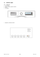
3.2 CONTROL PANEL 3.2.1 Styling TC1 • • • • max.
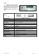
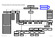
4 Summary table of the main areas and their contents LOGO LANGUAGE SETTING MAIN INTERFACE TIME SETTING CYCLE DURATION SELECTION TEMPERATURE SELECTION SPIN SELECTION COTTON 95° 1800 DELICATES 60° 1600 SYNTHETICS 50° 1400 WOOL 40° 1200 HAND WASH 30° 1000 LINGERIE COLD 900 PROGRAMME SELECTOR OPTION SELECTION INTENSIVE NORMAL MEMORIES 700 BABY 500 MINI 30 0 SILK COTTON - ECO DAILY LIGHT QUICK SUPER QUICK END OF EASY IRON DELAYED START Max 20 h ON SUPER RINSE OFF ON HALF
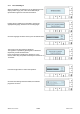
4.1.1 First switching on When the appliance is switched on for the first time the LCD display shows a logo (one of the various featured) as represented in figure and a musical introduction. Pushing the 3 or 4 buttons it is possible to choose the appropriate language, between a list of 25 languages. Once the language has been chosen, push OK 5 button twice. The screen for the time setting is displayed. The regulation is possible by pushing the 3 or 4 buttons respectively forward and backward.
4.2 Configuration of control panel The washing programmes, the functions of the selector knob and the various pushbuttons vary according to the model, since these are determined by the configuration of the appliance. 4.2.1 Programme selector (S1) The selector features 15-21 positions and incorporates the ON/OFF switch. The various positions of the selector may be configured to perform different washing programmes (ex: water level, drum movement, no.
If they do not need to be modified, just push the START/PAUSE (6) button to start the washing programme. If the basic settings do not satisfy the needs, pushing the relative buttons in sequence it is possible to modify the wash cycle temperature, the spin speed and to choose the various options to combine with the programme. 4.2.2 BUTTONS AND LCD ♦ Button 1 “TEMPERATURE” The temperature set by the programme is the base one.
After 2 seconds the writing changes to “PUSH OK”; pushing button 5 it is possible to change the option state from active to inactive or vice versa. Once the options have been chosen to close the expanded area just push a button (for ex. temperature, spin, etc.) or wait some seconds, the main screen will be displayed with the selected options.
4.2.3 Time DRIVEN The “Time driven” has the function to modify the programme settings according to the type of dirt so the wash time can be reduced or increased. Displaying the dirt level through an icon represented by a shirt and the time through the four digits positioned on the right side of the LCD display, this variation can be modified with buttons 7 and 8 positioned besides the display. The symbol remains lit for the whole duration of the programme.
The levels are represented in the following table: COTTONS INTENSIVE NORMAL (basic programme) DAILY LIGHT QUICK SUPER QUICK SYNTHETICS --------------NORMAL (basic programme) DAILY LIGHT --------------SUPER QUICK DELICATES --------------NORMAL (basic programme) DAILY LIGHT --------------SUPER QUICK 4.2.4 Washing phases The washing cycle consists of six phases: water fill, washing, rinses, drain, spin and end of cycle.
4.2.5 Control of the options set during the cycle During the cycle the user can check the settings pushing a button: Temperature (1), Spin (2), Option (4-5) and OK (5). The main screen with all the indications appears. After five seconds the display returns to the previous screen. During the washing cycle, for many factors (drain filter dirty, etc.) the duration of the programme could slightly vary, thus causing the changing of the time to end proposed at the beginning of the cycle. 4.2.
4.2.7 Stop or cancelation of a programme When the washing programme has already begun. The user can stop it or cancel it by turning the programme selector to position 0 (zero, appliance off). When the user switches the appliance on again, s/he will be required to confirm the cancellation or to continue the programme. To cancel the programme, the user must push the button OK (5).
4.2.9 Child lock Push buttons 3 or 4, scroll down the menu till: “CHILD LOCK” Wait two seconds and the writing: “PUSH OK” button 5 appears. After activating the child lock the screen changes to inform the user how to unlock the appliance at the end of the cycle (push simultaneously buttons 3 and 4 for five seconds). This screen lasts about ten seconds. Then the screen shows the Child Lock active with the lock symbol not crossed and the writing below is ON.
4.2.10 Memory Some positions of the programme selector are dedicated to the memorization of washing cycles that the user can personalize, so as to avoid repeating the modifications to a programme, for ex. to the temperature, the spin speed and to the options. If the appliance is new the memories are empty, so the user needs to define them. Select a programme Modify it if necessary Push buttons 3 or 4, scroll down the menu till: “SAVE FAVOURITE” Push button OK (5).
4.2.11 Wash Guide Here the user can search for information about: the best programme to choose, the ideal cycle temperature, the optimal spin and the various options to combine, to obtain the best from the washing cycle. The guide to the washing is inside the option menu. Push buttons 3 or 4 and scroll down the menu till: “WASH GUIDE” Wait two second, the writing changes to: “PUSH OK” button 5. 4.2.11.1 Temperature Guide The writing “TEMP GUIDE” appears.
4.2.11.2 Spin guide Here the user can search for information about the different spin speeds for the clothes, so as to choose the best one. Push buttons 3 or 4 and scroll down the menu till: “WASH GUIDE” Wait two seconds the writing changes to: “PUSH OK” button 5. Push buttons 3 or 4 and scroll down the menu till: “SPIN GUIDE” Push button OK (5). The first description is displayed. Pushing buttons 3 or 4 all the descriptions for the various spin speeds are displayed.
4.2.11.3 Options guide Here the user can search for information about the available options to choose according to the clothes to be washed, so as to obtain the best result from their appliance. Push buttons 3 or 4 and scroll down the menu till: “WASH GUIDE” Wait two seconds the writing changes to: “PUSH OK” button 5. Push buttons 3 or 4 and scroll down the menu till: “OPTIONS GUIDE”. Push button OK (5). The first description is displayed.
4.2.11.4 Stain guide Here the user can search for information about how to remove heavy soil from different type of fabrics. Push buttons 3 or 4 and scroll down the menu till: “WASH GUIDE” Wait two seconds the writing changes to: “PUSH OK” button 5. Push buttons 3 or 4 and scroll down the menu till: “STAIN GUIDE” Push button OK (5). The first description is displayed. Pushing buttons 3 or 4 the other descriptions for the information relative to each type of stain are displayed.
4.2.11.5 Demo A special cycle has been created for demonstration of the operation of these appliances in retail outlets without connecting the appliance to the water supply. In this way, the salesman can select any programme; after starting the cycle by pressing START, the appliance will perform certain phases only, and will skip those which cannot be performed (water fill, drain, heating). The cycle takes place as follows: ª the door locking device is actioned in the normal way (i.e.
4.2.12 Settings The setting menu is inside the option menu. Push buttons 3 or 4 and scroll down the menu till: “SETTINGS” Wait two seconds the writing changes to: “PUSH OK” button 5. 4.2.12.1 Language “LANGUAGE” appears on the display. Push button OK (5). The writing under the flag symbol starts to flash; now it is possible to scroll down the list of the available languages pushing buttons 3 or 4 in sequence. Choose the language and push button OK (5).
4.2.12.2 Volume Push button 3 or 4 and scroll down the menu till: “SETTINGS” Wait two seconds the writing changes to: “PUSH OK” button 5. Push button 3 or 4 and scroll down the menu till: “VOLUME” Push button OK (5). The digit under the loudspeaker symbol starts to flash. Now it is possible to vary the volume level pushing buttons 3 or 4 in sequence (at every variation the sound is activated to represent the reached level and the digit changes from zero to nine).
4.2.12.3 Time Push button 3 or 4 and scroll down the menu till: “SETTINGS” Wait two seconds the writing changes to: “PUSH OK” button 5. Push button 3 or 4 and scroll down the menu till: “TIME” Push button OK (5). The digits under the clock symbol start to flash. Now it is possible to insert the day time pushing buttons 3 or 4 in sequence. To confirm push button OK (5). Waiting some seconds or pushing buttons: TEMPERATURE (1) or SPIN (2) the main screen is displayed again.
4.2.12.4 Luminosity Push button 3 or 4 and scroll down the menu till: “SETTINGS” Wait two seconds the writing changes to: “PUSH OK” button 5. Push button 3 or 4 and scroll down the menu till: “LUMINOSITY’” Push button OK (5). The digit under the sun symbol starts to flash. Now it is possible to vary the luminosity level pushing buttons 3 or 4 in sequence. Simultaneously, the LCD display varies and also the digit changes from zero to nine. Confirm the luminosity level with button OK (5).
4.2.12.5 Contrast Push button 3 or 4 and scroll down the menu till: “SETTINGS” Wait two seconds the writing changes to: “PUSH OK” button 5. Push button 3 or 4 and scroll down the menu till: “CONTRAST” Push button OK (5). The digit under the symbol starts to flash. Now it is possible to vary the contrast level pushing buttons 3 or 4 in sequence. Simultaneously, the LCD display varies and also the digit changes from zero to nine. Confirm the contrast level with button OK (5).
4.2.12.6 Resetting the settings This function allows the user to reset the basic settings set by the factory for: VOLUME, CONTRAST, LUMINOSITY and the configuration of the CHILD LOCK. Push button 3 or 4 and scroll down the menu till: “SETTINGS” Wait two seconds the writing changes to: “PUSH OK” button 5. Push button 3 or 4 and scroll down the menu till: “RESET SETTINGS” Wait two seconds the writing changes to: “PUSH OK” button 5. After pushing OK the user is asked to confirm the choice.
4.2.12.7 Delayed start To modify the time to end of the cycle indicated in the right lower side it is necessary: Push buttons 3 or 4 and scroll down the menu till: “END TIME”. Push OK button 5 the four digits which indicate the time start to flash. It is possible to modify the time with buttons 3 or 4. Pushing it in sequence the time increases or decreases (respectively with button 3 and 4) by thirty minutes for the first two hours and sixty minutes till the twenty hours are reached (the max.
5 DIAGNOSTIC SYSTEM 5.1 Access to diagnostic mode 1. Switch off the appliance. 2. Press and hold down START/PAUSE button and the nearest OK button (as represented in figure). 3. Holding down both buttons, switch the appliance on by turning the programme selector by one position clockwise. 1. Continue to hold down the buttons till the display lights up and the “DIAGNOSTIC TEST” appears.
5.3 Diagnostic phases Irrespective of the type of PCB and the configuration of the programme selector it is possible, after entering diagnostic mode, to perform diagnostics on the operation of the various components and to read the alarms by turning the programme selector clockwise. All the alarms are enabled during the diagnostic cycle. Selector position Components actioned Operating conditions - All the LEDs and symbols light in sequence.
5.3.1 Analysis of the LCD display during the diagnostic cycle In position 1 the LCD display is displayed through the chessboard lighting (with different dimensions) of all the display points. Every time that during this test a button is pushed the test is interrupted and in the bottom centre the button codification in shown. From position 2 to position 9 the display represents: The temperature on the left lower side. The drum speed in the centre. The water level on the right.
6 ALARMS 6.1 Displaying the alarms to the user The alarms are displayed by the red LED of the START/PAUSE button flashing and simultaneously through the LCD.
The alarms are enabled during the execution of the washing programme, with the exception of alarms associated with configuration and the power supply (voltage/frequency), which are also displayed during the programme selection phase.
6.2.1 Displaying the alarm The alarm is displayed by a repeated flashing sequence of the START / PAUSE button with red and green light (0,5 seconds on, 0,5 seconds off with a 2,5 second pause between the sequences). • button indicator START / PAUSE with red light → indicates the first digit of the alarm code (family) • button indicator START / PAUSE with green light → indicates the second digit of the alarm code (internal number of the family) These two LEDs are featured in all models.
6.3 Rapid reading of alarm codes The last three alarm codes can be displayed even if the programme selector is not in the tenth position (diagnostics) or if the appliance is in normal operating mode (e.g. during the execution of the washing programme): → Press and hold down START/PAUSE and the OK button (as to enter the DIAGNOSTICS), for at least two seconds: the display shows directly a screen with all the alarms. → To return to the main screen press any button.
6.5 Cancelling the memories To cancel the content of the memories, proceed as follows: 1. Select diagnostic mode and turn the programme selector to the tenth position. 2. Push the OPTIONS 3 and 4 button (as represented in figure). 3. Hold down the buttons till the LCD display shows “Memories have been reset” (at least 5 seconds).
8 WASHING PROGRAMMES AND OPTIONS 8.1 Programmes The washing programmes can be configured. The basic programmes are listed in the table below.
8.2 Options The table below lists the possible options for the washing programmes, the compatibility of the various options and with the cycle, and when it is possible to select or modify the options. The options can be selected in three ways: using the programme selector: in this case, the options are configured as special programmes; using the pushbuttons.
Compatibility with PROGRAMMES Hygienize Grass Express Sensitive plus Rapid Viscose Soak Rinses Delicates Rinses Conditioner Delicate conditioner Drain Spin Delicate spin X X X X X X X X X X X X X X X X X X X X X X X X X X X X X X X X X X X X X X X X X X X X X X X X X X X X X X X X X X X X X X X X X X X X X X X X X X X X X X X X X X X X X X X X X X X X X X X X X X X X X X X X X X X X X X X X X X X X X X X X X X X X X X X X X X X X X X X X X X X X X X X X X X X X X X X X X X X X X X
8.2.
8.3 Description of options • Rinse-hold → Stops the appliance with water in the tub before the final spin cycle. → To drain the water, reset the programme and then select a drain or spin cycle. • Night cycle → Eliminates all spin phases and adds three rinses in COTTON cycles and two rinses in SYNTHETICS cycles. → Stops the appliance with water in the tub before the final rinse. → Eliminates the buzzer (if configured) → To drain the water, reset the programme and then select a drain or spin cycle.
• Reduced spin speed → Reduces the speed of all spins as shown in the table. Maximum spin speed (rpm) Reduction for COTTON (rpm) Reduction for ALL OTHER CYCLES (rpm) 600 450 450 700 450 450 800 450 450 900 1000 1100 1200 1300 1400 1550 450 500 550 600 650 700 750 450 450 450 450 450 450 450 • No spin → Eliminates all the spin phases. → If selected, three rinses are added in the COTTON cycle and one in the SYNTHETICS cycle. • Intensive → Performs a specific intensive cycle.
9 9.1 TECHNICAL CHARACTERISTICS Control system memory 9.1.1 General structure of the memory system The system features an EEPROM memory module, fitted externally to the microprocessor, which serves to memorize the configuration data, the description of the cycle, the status of the appliance in the event of a power failure, and the alarms. Power Failure and Machine status μP External serial port (asynchronous FLASH RAM Configuration of the appliance configuration Description of the cycle 9.1.
Ö Washing cycle tables: Each washing cycle consists of a series of phases (steps); the steps are the basic instructions which comprise the description of the cycle, which is common to all appliances having the same characteristics: - Water fill - Motor movement - Reset - Heating - Drain - Spin - “IF” conditions (options, temperatures etc.
9.2 Door interlock There are two types of door interlock: • voltmetric with PTC • instantaneous 9.2.1 Voltmetric interlock with PTC 10 Suppressor 19 Door interlock 20 PCB ON/OFF = Main switch (programme selector) 9.2.1.
9.2.2 • Instantaneous door interlock With this safety device it is possible to open the door immediately after the end of the cycle. 9 Door interlock 19 Suppressor 20 PCB ON/OFF = Main switch (programme selector) 9.2.2.1 Operating principle ª When the ON/OFF switch closes and the appliance is switched on, power is applied to the bimetallic PTC switch (contact 4-2), but the door remains unlocked.
9.3 Water fill system The electric valves are powered by the PCB by means of the triac and the control of the water level in the tub is carried out by the analogue pressure switch. 3 5 6 7 20 Analogue pressure switch Prewash electric valve Wash electric valve Bleach electric valve PCB 9.
9.5 15 16 20 Drain pump Drain pump Thermal protector PCB The PCB powers the drain pump via a triac as follows: - 9.6 until the electronic pressure switch closes on empty, after which the pump is actioned for a brief period or passes to the subsequent phase; for a pre-determined period (and eventually an alarm appears). Recirculation pump (if featured) On jetsystem models, the main board powers the recirculation pump through a triac.
9.7 Heating 2 13 14 K1 NTC temperature sensor Heating element (with thermal fuses) PCB Relay 1. 2. 3. 4. Tubular casing Thermal fuses NTC Sensor Connectors The heating element is powered by a relay (K1) of the electronic board and is provided with two thermal fuses, which interrupt if the temperature degree exceeds the values by which they are calibrated.
9.9 11. 20. 23. 24. Three-phase asynchronous motor Tachometric generator PCB Inverter Motor X-Y-X = Motor windings 9.9.1 Power supply to motor Three-phase power is fed by the inverter (4) which sends, through the connectors 5-6-7, the three phases to connectors 1-2-3 on the motor (nodes V-W-U), where the windings (Y-X-Z-) are connected. The phase shift between the phases is 120° and peak amplitude is 310V.
9.10 Anti-foam control system The anti-foam control procedure (if featured) is performed via the anti-boiling pressure switch. Spin phase without foam Spin phase with little foam Spin Spin Anti-foam (Electronic level) 450 rpm pulses 450 rpm pulses FUCS FUCS • • Spin with little foam: if the contact of the electronic pressure switch closes on FULL, the spin phase is interrupted; the drain pump continues to operate and, when the contact returns to EMPTY, the spin phase is resumed.
9.11 FUCS ( Fast Unbalance Control System) rpm The control procedure for unbalanced loads is performed dynamically, before each spin cycle, as follows: ª The phase begins at a speed of 55 RPM. The speed may not drop below this threshold; if it does, the check is repeated. ª At intervals of 300 ms, the balance is calculated and compared with established limits.
• An example of drum balancing in the longest interval of time available 1 2 Phase 1 2 3 4 5 6 7 • 3 4 5 Unbalance rating 0 1 2 3 1 2 3 6 7 Time-out (sec) 60 120 60 90 120 60 90 An example of unbalancing after all FUCS phases have been performed In this case, the spin (or pulse operation) is skipped.
9.12 Table of alarm codes Alarm E11 E13 E21 E23 E24 E31 E32 E35 E38 E3A E41 E42 E43 E44 E45 E51 E52 E53 E54 E57 Possible fault Tap closed or water pressure too low; Drain tube improperly positioned; Water fill solenoid valve is faulty; Leaks from water circuit on pressure switch; Pressure switch faulty; Wiring faulty; PCB faulty. Drain tube improperly positioned; Water pressure too low; Water fill solenoid valve is faulty; Water circuit on pressure switch is leaking/clogged; Pressure switch faulty.
Alarm E5F Possible fault Motor defective; Wiring defective on inverter for motor, inverter board defective, abnormal motor operation (motor overloaded). Motor defective; Wiring defective on inverter for motor; Inverter board defective. Inverter board defective. NTC open (on the inverter board).
Alarm Possible fault Action/machine status Reset EH1 Power supply problems (incorrect / disturbance); PCB faulty. Wait for frequency nominal conditions. OFF/ON EH2 Power supply problems (incorrect / disturbance); PCB faulty. Wait for voltage nominal conditions. OFF/ON EH3 Power supply problems (incorrect / disturbance); PCB faulty. Wait for voltage nominal conditions. OFF/ON EHE EHF Wiring faulty; PCB faulty. PCB faulty. Safety drain cycle – Cycle stopped with door open.
10 Diagram with THREE-PHASE ASYNCHRONOUS MOTOR SOI/DT 2007-02 dmm 60/66 599 38 61-92
• Key to diagram with THREE-PHASE ASYNCHRNOUS MOTOR Electrical components on appliance 1. Display board 1a. LCD display 2. Flowmeter 3. Analogue pressure switch 4. NTC temperature sensor 5. Solenoid valve for prewash 6. Solenoid valve for wash 7. Solenoid valve for bleach 8. Heating element (with thermofuses) 9. Door interlock (instantaneous) 10. Suppressor 15. Drain pump 16. Thermal cut-out (drain pump) 17. Recirculation pump 18. Thermal cut-out (recirculation pump) 19. Door interlock (with PTC) 20.
11 ACCESSIBILITY 11.1 To the electronic control system 11.1.1 Work top a. Remove the two rear screws, push the top panel towards the rear and release from the cabinet. 11.1.2 Control panel b b. c. Press the drawer lock. Extract. c d. Remove the screw which secures the control panel to the dispenser. d e e. Remove the clamp which secures the wiring to the board casing. f. Release the wiring from the clamp under the dispenser. f After releasing the wiring from the fixing hooks.
g g. Loosen the screws which secure the cross-member to the cabinet. h h. Release the hook which secures the dispenser to the cross-member. h i i. Lift the control panel up. j j. k. Loosen the screws which secure the cross-member to the control panel. Release the hook which secures the control panel to the crossmember. k m l. Turn and insert a protection between the control panel and the surface which you lean it on to avoid damaging it. m.
11.2 Door interlock a. Remove the ring that secures the bellow gasket to the cabinet. b. Remove the bellow gasket. c. Remove the screw which secures the door interlock to the front side. d. Push inside the hook. e. Push it upwards. f. Extract the door interlock.
11.3 New drain filter a. Open the filter door with the appropriate tool (supplied with the appliance), because it is locked. To empty the drain circuit: b. Remove the cap in the filter knob (after positioning a vessel to collect the water). c c. Turn the cap left to align the two references: (the arrow in the cap and the reference point in the filter body), so as to allow extracting the filter. d. Extract the filter.
11.4 Inverter board a. Release the hook. b. Push the hook inside, extract it. c. Push the wing which secures the board the cabinet.