SERVICE MANUAL W75 – W100 – W160 – W230 471 1553-51
NOTICE TO SERVICE PERSONNEL INSTALLATION Improper installation of Wascomat laundry and wet cleaning equipment can result in personal injury and severe damage to the machine. REFER INSTALLATION TO QUALIFIED PERSONNEL! RISK OF ELECTRIC SHOCK The equipment utilizes high Voltages. Disconnect electric power before servicing. The use of proper service tools and techniques, and the use of proper repair procedures, is essential to the safety of service personnel and equipment users.
Summary Machine description – Safety regulations 1 Data 2 Description of principle components 3 Programmes 4 5 Serviceinstructions Periodic maintenance 11 Function sequences – Fault finding 12 Automatic unit 21 22 Timer 23 24 25 Level control 26 Thermostat 27 28 Included units and components Door and safety locking device 29 Motor 30 31 32 33 Inlet valve, water 34 35 36 37 Drain valve 38 39 Heating 40 Coin meter 41 Drum and bearings 42 Frame 43 44 45 46 47 48 49 50
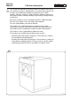
Service Manual Fig. 1. Machine description 9 9112 1 Type Edition Page 1 The 70 100, 160 and 230 litre washing machines described in this manual are normal spin machines and differ only in size and washing capacity. The machines are intended for installation in apartment houses, hotels, laundries, industries, hospitals, smaller institutions and other regular users who require machines with high reliability, large washing capacity and easy maintenance.
1 9 9112 2 Type Edition Page 1. Machine description Safety Regulations • The machine is designed for water washing only. • The machine must not be used by children. • Installation and service work may only be carried out by qualified personnel. • The machine’s door lock may not be bypassed under any circumstances. • System leakage, such as a worn door gasket, should be repaired immediately.
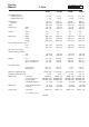
Service Manual 8 2. Data 9112 1 Type Edition Page W 75 2 W 100 W 160 W230 5.4 kg 7 kg 7.7 kg 10 kg 12.3 kg 16 kg 17.7 kg 23 kg wash spin 70 520 356 52 530 100 520 473 52 530 160 620 520 52 500 230 700 600 45 455 G-factor wash spin 0.8 81 Dimensions width depth height Dry weight capacity at filling factor 1:13 at filling factor 1:10 Drum volume diameter depth Drum speed lit mm mm r/m r/m lit mm mm r/m r/m 0.8 81 lit mm mm r/m r/m 0.9 87 lit mm mm r/m r/m 0.
2 8 9112 2 Service Manual 2.
Service Manual 8 2.
Service Manual 3. Description of principle components 11 9020 9112 1 Type Edition Page 3 The inner drum drive shaft is mounted in the outer drum with two ball bearings at the back plate. Two neoprene gaskets make the shaft leak resistant. Fig. 1 The motor is mounted on a rubber-cushioned shaft under the drum. To prevent transmission of troublesome noises from chassis to the building frame, the motor’s belt-tensioning device is also rubber-cushioned.
Service Manual 10 4. Programmes 9002 1 Type Edition Page 4 Identification of wash programs The wash programs are identified by a combined letter and number symbol. Identification occurs as described in the example below. User catagory P = Standard Water connection H = Hygienic and hospital. These programs follow national regulations C = cold water CH = cold and hot water CHd = cold and cold hard water S = Selecta program. Special OPLprogram.
4 10 9002 2 4. Programmes Type Edition Page Program description The wash programs identified by the symbol P11C are described on the following pages. They are the programs designed for a regular user using a heated machine with mechanical timer and intended for cold water connection only. These machines have eight fixed programs, which are selected by using the knob on the control panel.
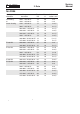
C = COLD WATER HL = HIGH LEVEL LL = LOW LEVEL WITHOUT PRE WASH MAIN WASH COOL DOWN DRAIN RINSE 1 DRAIN EXTRACTION RINSE 2 DRAIN EXTRACTION RINSE 3 DRAIN EXTRACTION RINSE 4 DRAIN EXTRACTION SHAKE OUT TOTAL TIME PROGRAM SEQUENCE = = = = D E G N INLET WATER TIME ACTION 27.5 - HL - HL - HL 3 - - TEMP N 1 C N 1 E 0.5 N 2 C N 1 E 0.5 N 2 C N 1 E 1 N 1.5 LEVEL 2 2 DETERGENT N 3 C - LL N 12 C 60 LL C 56 N 1 LEVEL TEMP INLET WATER ACTION N 1 C N 1 E 0.5 N 2 C N 1 E 0.5 N 2 C N 1 E 1 N 1.5 27.
1 C 1 0.5 2 C 1 0.5 2 C 1 1 1.5 D E G N INLET WATER TIME ACTION TEMP - LL LEVEL N 1 C N 1 E 0.5 N 2 C N 1 E 0.5 N 2 C N 1 E 1 N 1.5 33 - HL - HL - HL N 12 C 60 LL C 56 N 1 N 1 C - HL N 1 N 6 C N 0.5 DETERGENT 3 - - - 2 1 INLET WATER TIME - TEMP LL N 1 C N 1 E 0.5 N 2 C N 1 E 0.5 N 2 C N 1 E 1 N 1.5 33 - HL - HL - HL N 12 C 40 LL - - N 1 N 1 C - HL N 1 N 6 C N 0.
Service Manual 11 4. Programmes 9002 1 Type Edition Page 4 Identification of wash programs The wash programs are identified by a combined letter and number symbol. Identification occurs as described in the example below. User catagory P = Standard Water connection H = Hygienic and hospital. These programs follow national regulations. C = cold water CH = cold and hot water CHd = cold and cold hard water S = Selecta program. Special OPLprogram.
4 11 9002 2 Service Manual 4. Programmes Type Edition Page Program description 1 The wash programs identified by the sybol P11C are described on the following pages. They are the programs for a regular user in Sweden using a heated machine with mechanical timer and intended for cold water connection only. There are more program variations available for machines with electronic timer.
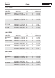
C = COLD WATER HL = HIGH LEVEL LL = LOW LEVEL PRE WASH DRAIN WITHOUT PRE WASH MAIN WASH COOL DOWN DRAIN RINSE 1 DRAIN RINSE 2 DRAIN EXTRACTION RINSE 3 DRAIN EXTRACTION RINSE 4 DRAIN EXTRACTION SPIN DOWN TOTAL TIME PROGRAM SEQUENCE D E G N = = = = ACTION N N E N N E N N E N N N N N LEVEL TEMP INLET WATER TIME PROGIND 6 6 6 7 7 7 8 9 9 9 1.5 C 0.3 0.5 1.5 C 0.3 0.5 2 C 0.3 1 0.5 LL 24 - HL - HL - 3 3 C - LL 3 12 C 55 LL 4 4 0.5 DETERGENT 3 - - 2 2 6 6 6 7 7 7 8 9 9 9 INLET WATER 1.
INLET WATER TIME TEMP - LL LEVEL D E G N = = = = 12 C 90 LL C HL 0.5 1.5 C - LL 0.5 1.5 C - LL 0.3 0.5 1.5 C - HL 0.3 0.5 2 C - HL 0.3 1 0.5 29.3 6 C 0.3 DETERGENT ACTION N N N N N N N E N N E N N E N N N PROGIND 3 4 4 5 5 6 6 6 7 7 7 8 9 9 9 0.5 1.5 0.5 1.5 0.3 0.5 1.5 0.3 0.5 2 0.3 1 0.5 - - HL - HL C C C 29.3 LL - C LL 3 - - - 2 TIME 12 C 60 LL LEVEL 1 TEMP - DETERGENT LL INLET WATER 1 6 C 2 0.
C = COLD WATER HL = HIGH LEVEL LL = LOW LEVEL PRE WASH DRAIN WITHOUT PRE WASH MAIN WASH COOL DOWN DRAIN RINSE 1 DRAIN RINSE 2 DRAIN EXTRACTION RINSE 3 DRAIN EXTRACTION RINSE 4 DRAIN EXTRACTION SPIN DOWN TOTAL TIME PROGRAM SEQUENCE - HL 2 C 0.3 D E G N = = = = 21.5 ACTION N N N N N N N N N N - HL 21.5 3 N N N N INLET WATER 8 2 C 8 0.3 7 1.5 C 7 0.3 6 1.5 C 6 0.3 8 2 C 8 0.3 - - - HL LL LEVEL TEMP LL 21.5 - HL - HL - 3 C - LL 12 C 40 LL 7 1.5 C 7 0.
INLET WATER TIME TEMP - HL 2 C 0.3 D E G N = = = = 26.8 - HL 1.5 C 0.3 ACTION N N N N N N N N N N N N N INLET WATER TIME PROGIND TEMP - LL LEVEL 0.5 1.5 C 0.5 1.5 C 0.3 8 2 C 8 0.3 LL LL 26.8 - HL - HL - - 12 C 60 LL 7 1.5 C 7 0.3 3 4 4 5 5 6 6 1 6 C 2 0.3 DETERGENT 3 - - - 2 1 N N N N N N N N N N N N ACTION DISTRIBUTION EXTRACTION GENTLE ACTION 3/12 SEC NORMAL ACTION 12/3 SEC 3 - - - 2 12 C 90 LL C HL 0.5 1.5 C - LL 0.5 1.5 C - LL 0.
Service Manual 12 9002 4. Programmes 1 Type Edition Page 4 Identification of wash programs The wash programs are identified by a combined letter and number symbol. Identification occurs as described in the example below. User catagory P= Standard Water connection H= Hygienic and hospital. These programs follow national regulations. C = cold water CH = cold and hot water CHd = cold and cold hard water CHHd = cold, hot and cold hard water S= Selecta program. Special OPLprogram.
= = = = NO ACTION GENTLE ACTION NORMAL ACTION EXTRACTION C W H LL HL = = = = = 3 - HL 27.5 - - HL ACTION - TIME - HL INLET WATER N 1 C N 1 E 0.5 N 2 C N 1 E 0.5 N 2 C N 1 E 4 N 1.5 TEMP 2 LEVEL N 12 W 60 LL - N 1 DETERGENT COLD WATER (15° C) WARM WATER (35° C) HOT WATER (65° C) LOW LEVEL HIGH LEVEL 3 - HL 27.5 - - HL TIME - INLET WATER - HL TEMP 1 C 1 0.5 2 C 1 0.5 2 C 1 4 1.5 LEVEL 2 DETERGENT 12 W 90 LL - 1 LEVEL TEMP INLET WATER TIME ACTION N 1 C N 1 E 0.
= = = = NO ACTION GENTLE ACTION NORMAL ACTION EXTRACTION C W H LL HL = = = = = INLET WATER TIME ACTION TEMP - LL LEVEL N 12 H 60 LL - N 1 N 1 C - HL 1 - N 1 C - HL N 1 E 0.5 N 2 C - HL N 1 E 0.5 N 2 C - HL N 1 E 4 N 1.5 36 N 6 W N 0.5 3 - - - 2 1 DETERGENT COLD WATER (15° C) WARM WATER (35° C) HOT WATER (65° C) LOW LEVEL HIGH LEVEL 3 - - - 2 TIME 12 H 90 LL - 1 1 C - HL 1 1 C - HL 1 0.5 2 C - HL 1 0.5 2 C - HL 1 4 1.5 36 LEVEL 1 TEMP - DETERGENT LL INLET WATER 6 W 0.
Service Manual 13 4. Programmes 9002 1 Type Edition Page 4 Identification of wash programs The wash programs are identified by a combined letter and number symbol. Identification occurs as described in the example below. User catagory P= Standard Water connection H= Hygienic and hospital. These programs follow national regulations. C = cold water CH = cold and hot water CHd = cold and cold hard water CHHd = cold, hot and cold hard water S= Selecta program. Special OPLprogram.
= = = = LEVEL TEMP INLET WATER TIME NO ACTION GENTLE ACTION NORMAL ACTION EXTRACTION C W H LL HL = = = = = N N N N N N N INLET WATER TIME PROGIND 6 6 6 7 7 7 8 9 9 9 4 1.5 C 0.3 0.5 1.5 C 0.3 0.5 2 C 0.3 4 0.5 1 LL 26.4 - HL - HL - 3 14 W 55 LL TEMP COLD WATER (15° C) WARM WATER (35° C) HOT WATER (65° C) LOW LEVEL HIGH LEVEL 3 - HL 26.4 - - HL N N - LL 1.5 C 0.3 0.5 1.5 C 0.3 0.5 2 C 0.3 4 0.
= = = = NO ACTION GENTLE ACTION NORMAL ACTION EXTRACTION 1.5 C 0.3 0.5 1.5 C 0.3 0.5 2 C 0.3 4 0.5 3 - HL C W H LL HL - - HL = = = = = ACTION N N N N N N N N N N N N N N N 6 6 6 7 7 7 8 9 9 9 1.5 C 0.3 0.5 1.5 C 0.3 0.5 2 C 0.3 4 0.5 3 - HL 36.9 - L - - LL - LL - - 4 1 5 1.5 C 5 0.5 PROGIND 4 TIME 3 16 H 60 LL INLET WATER 1 DETERGENT 1 6 W 30 LL 2 0.5 TEMP COLD WATER (15° C) WARM WATER (35° C) HOT WATER (65° C) LOW LEVEL HIGH LEVEL 36.
= = = = LEVEL TEMP INLET WATER TIME NO ACTION GENTLE ACTION NORMAL ACTION EXTRACTION C W H LL HL = = = = = 20.9 - HL 2 C 0.3 N N N N TEMP INLET WATER TIME PROGIND 1 8 2 C 8 0.3 7 1.5 C 7 0.3 6 1.5 C 6 0.3 4 LL 20.9 - HL - HL - 3 14 W 55 LL LEVEL COLD WATER (15° C) WARM WATER (35° C) HOT WATER (65° C) LOW LEVEL HIGH LEVEL 3 N N - HL 1.5 C 0.3 - N N - - 1.5 C 0.
= = = = NO ACTION GENTLE ACTION NORMAL ACTION EXTRACTION C W H LL HL - HL 2 C 0.3 = = = = = 3 - - ACTION N N N N N N N N N N N N N N - HL 8 2 C 8 0.3 31.4 L - 7 1.5 C 7 0.3 LL - 6 1.5 C 6 0.3 LL 3 - - - - 4 1 5 1.5 C 5 0.5 PROGIND 4 TIME 3 16 H 60 LL INLET WATER 1 DETERGENT 1 6 W 30 LL 2 0.5 TEMP COLD WATER (15° C) WARM WATER (35° C) HOT WATER (65° C) LOW LEVEL HIGH LEVEL 31.4 - HL 1.5 C 0.3 LL - LL 1.5 C 0.3 - - TIME 1 1.5 C 0.
Service Manual 14 9002 4. Programmes 1 Type Edition Page 4 Identification of wash programs The wash programs are identified by a combined letter and number symbol. Identification occurs as described in the example below. User catagory P= Standard Water connection H= Hygienic and hospital. These programs follow national regulations. C = cold water CH = cold and hot water CHd = cold and cold hard water CHHd = cold, hot and cold hard water S= Selecta program. Special OPLprogram.
CYCLE = = = = NO ACTION GENTLE ACTION NORMAL ACTION EXTRACTION 3 - HL TEMP INLET WATER TIME ACTION N 1 C N 1 E 0.5 N 2 C N 1 E 0.5 N 2 C N 1 E 4 N 1.5 - 3 - HL - HL 30.5 - 2 2 DETERGENT - HL N 3 C - LL N 12 C 60 LL - N 1 LEVEL C = COLD WATER (15°C) LL = LOW LEVEL HL = HIGH LEVEL 30.5 - - HL TIME - INLET WATER - HL TEMP 1 C 1 0.5 2 C 1 0.5 2 C 1 4 1.5 LEVEL 2 2 DETERGENT 3 C - LL 12 C 90 LL - 1 LEVEL TEMP INLET WATER TIME ACTION N 1 C N 1 E 0.5 N 2 C N 1 E 0.
G N E = = = = INLET WATER TIME ACTION - TEMP LL N 12 C 60 LL - N 1 N 1 C - HL N 1 - N 1 C - HL N 1 E 0.5 N 2 C - HL N 1 E 0.5 N 2 C - HL N 1 E 4 N 1.5 36 N 6 C N 0.5 LEVEL C = COLD WATER (15° C) LL = LOW LEVEL HL = HIGH LEVEL 3 - - - 2 12 C 90 LL - 1 1 C - HL 1 1 C - HL 1 0.5 2 C - HL 1 0.5 2 C - HL 1 4 1.5 36 LEVEL 1 DETERGENT LL TEMP - DETERGENT 3 - - - 2 1 INLET WATER TIME ACTION TEMP - LL LEVEL N 12 C 40 LL - N 1 N 1 C - HL N 1 - N 1 C - HL N 1 E 0.
Service Manual 15 9002 4. Programmes 1 Type Edition Page 4 Identification of wash programs The wash programs are identified by a combined letter and number symbol. Identification occurs as described in the example below. User catagory P= Standard Water connection H= Hygienic and hospital. These programs follow national regulations. C = cold water CH = cold and hot water CHd = cold and cold hard water CHHd = cold, hot and cold hard water S= Selecta program. Special OPLprogram.
= = = = INLET WATER ACTION NO ACTION GENTLE ACTION NORMAL ACTION EXTRACTION C W H LL HL = = = = = 23.5 - HL - HL - HL 3 - - 2 1 DETERGENT COLD WATER (15° C) WARM WATER (35° C) HOT WATER (65° C) LOW LEVEL HIGH LEVEL 3 - HL 23.5 - - HL 1 G 1 C G 1 E 0.5 G 1 C G 1 E 0.5 G 2 C G 1 E 4 G 1.5 - TEMP 5 W 60* LL 1 C 1 0.5 1 C 1 0.5 2 C 1 4 1.
Service Manual 16 9002 4. Programmes 1 Type Edition Page 4 Identification of wash programs The wash programs are identified by a combined letter and number symbol. Identification occurs as described in the example below. User catagory P= Standard Water connection H= Hygienic and hospital. These programs follow national regulations. C = cold water CH = cold and hot water CHd = cold and cold hard water CHHd = cold, hot and cold hard water S= Selecta program. Special OPLprogram.
= = = = - HL - HL C C NO ACTION GENTLE ACTION NORMAL ACTION EXTRACTION C W H LL HL = = = = = 24.5 - HL C 1.5 - HL TIME C INLET WATER 6 1 1 1 0.5 1 1 0.5 2 1 4 - HL TEMP C LEVEL 3 1 DETERGENT ACTION TIME 3 W 1 INLET WATER N 1.5 N 6 W N 1 - N 1 C N 1 E 0.5 N 1 C N 1 E 0.5 N 2 C N 1 E 4 N N LEVEL TEMP 24.
Service Manual 17 9002 4. Programmes 1 Type Edition Page 4 Identification of wash programs The wash programs are identified by a combined letter and number symbol. Identification occurs as described in the example below. User catagory P= Standard Water connection H= Hygienic and hospital. These programs follow national regulations. C = cold water CH = cold and hot water CHd = cold and cold hard water CHHd = cold, hot and cold hard water S= Selecta program. Special OPLprogram.
INLET WATER 1 1 C 0.5 0.5 2 C 0.5 0.5 2 C 0.5 5 NO ACTION GENTLE ACTION NORMAL ACTION EXTRACTION TEMP DETERGENT 3 - HL C W H LL HL - - HL = = = = = ACTION N N N E N N E N N E N N N PROGIND 5 6 6 6 7 7 7 8 9 9 4 TIME 19.5 - HL - HL - HL H 60 LL 1 1 C 0.5 0.5 2 C 0.5 0.5 2 C 0.5 5 6 INLET WATER COLD WATER (15° C) WARM WATER (35° C) HOT WATER (65° C) LOW LEVEL HIGH LEVEL 19.
INLET WATER 1 1 C 0.5 0.5 2 C 0.5 0.5 2 C 0.5 5 NO ACTION GENTLE ACTION NORMAL ACTION EXTRACTION TEMP 3 - HL C W H LL HL - - HL = = = = = ACTION N N N E N N E N N E N N N PROGIND 5 6 6 6 7 7 7 8 9 9 4 - 3 - HL - HL 19.5 - 4 - DETERGENT - HL H 60 LL 6 1 1 C 0.5 0.5 2 C 0.5 0.5 2 C 0.5 5 C TIME 2 1 INLET WATER COLD WATER (15° C) WARM WATER (35° C) HOT WATER (65° C) LOW LEVEL HIGH LEVEL 19.
NO ACTION GENTLE ACTION NORMAL ACTION EXTRACTION TEMP 3 - HL C W H LL HL - - HL = = = = = N N N E N N E N N E N N PROGIND 5 6 6 6 7 7 7 8 9 9 3 3 4 TIME 1 1 C 0.5 0.5 2 C 0.5 0.5 2 C 0.5 5 - 3 - HL - HL 23.5 - 4 1 DETERGENT - HL 3 W 40 LL 1 6 H 60 LL INLET WATER COLD WATER (15° C) WARM WATER (35° C) HOT WATER (65° C) LOW LEVEL HIGH LEVEL 23.5 - - HL 4 ACTION N N N ACTION N N N E N N E N N E N N N N N PROGIND 5 6 6 6 7 7 7 8 9 9 3 3 4 TIME TEMP 20.
INLET WATER NO ACTION GENTLE ACTION NORMAL ACTION EXTRACTION 1 1 C 0.5 0.5 2 C 0.5 0.5 2 C 0.5 5 3 - HL C W H LL HL - - HL = = = = = ACTION N N N E N N E N N E N N N N N N N PROGIND 5 6 6 6 7 7 7 8 9 9 3 3 4 2 2 TIME 1 1 C 0.5 0.5 2 C 0.5 0.5 2 C 0.5 5 1 3 W 40 LL 1 6 H 60 LL - 3 - HL - HL 26.5 - - HL 4 - C DETERGENT - HL 2 1 INLET WATER COLD WATER (15° C) WARM WATER (35° C) HOT WATER (65° C) LOW LEVEL HIGH LEVEL 26.
Service Manual 5 11. Periodic Maintenance For proper and safe machine operation, the maintenance procedures described below should be followed. Frequency of maintenance should be based on the machine's degree of use. Daily • Check door and safety lock: - Open the door and try to start machine. It should not start. - Close the door, start machine and try to open the door. It should not be possible to open the door. - Make sure the door does not leak. - Clean the door seal of any residual detergent.
Service Manual 10 12.
12 10 9003 Service Manual 4 12. Function Sequences Type Edition Page Start When a program is completed, the machine stops at program stage 52 and the door can be opened. The door must be closed for the machine to start. It is only when the door is closed that point B receives voltage (see section on "Safety lock and power supply"). When the START button is pressed to start a new program, the coil for timer (5) rapid advance receives voltage since row 34 (3) is closed at stages 52-53.
Service Manual 10 12.
12 10 9003 Service Manual 6 12. Function Sequences Type Edition Page Rapid advance and program selection Depending on which program is selected and if the HEAVILY SOILED button is pressed, the timer is rapid advanced past different program phases. In chapter 4, (Program description, type 10), is a description of how the various programs differ from one another. Rapid advance occurs as follows: All programs The timer rapid advances when rows 41 (8) and 35 (5) are closed.
Service Manual 10 12. Function Sequences Parent card Timer B B A:17 9003 7 Type Edition Page 12 = Power supply, see function diagram ''Safety lock and power supply''.
12 10 Service Manual 9003 8 12. Function Sequences Type Edition Page Motor control For the motor to operate, it is necessary for row 5a (2) or row 7a (1) to be closed, or for the level sensor to be shut off (water level is reached) so that point E receives voltage. The sequence diagram indicates that both rows 5a and 7a are closed during water filling, spin and tumble cycles.
Service Manual 10 12. Function Sequences Parent card B A 16 A E 15 9003 9 Type Edition Page 12 A B E = Power supply. Points A and B, see function diagram ''Safety lock and power supply''. Point E, see function diagram ''Water filling''.
12 10 9003 10 Service Manual 12. Function Sequences Type Edition Page Water filling This section describes a machine which only has a cold water connection. The diagrams of other variants (• cold and hot water • cold, hot and cold-hard water • cold and cold-hard water) are included in the machine circuit diagram. Here is how water fills during the various wash moments: Prewash During the prewash cycle, rows 14a (1) and 6b (7) are closed.
Service Manual 10 12. Function Sequences B Parent card B A:17 Timer a 10 a 3 7 8 4 X183 Program selector = Power supply, see function diagram ''Safety lock and power supply''.
12 10 9003 12 Service Manual 12. Function Sequences Type Edition Page Heating Contactor K21 (11) controls the heating elements on electrically heated machines. Steam heated machines have steam valve Y5 (11). Heating cannot take place until the drum is filled with water so that the level control shuts off (see function diagram ”Water filling”). Voltage is then received by the heating function, point E to the right in the diagram.
Service Manual 10 12. Function Sequences Timer 9003 13 Type Edition Page 12 E = Power supply from level sensor, see function diagram ''Water filling''. E 5 (1) Programmer, row 5b Temp., main wash b X83:6 X183:5 Programselector (2) Program selector row 9 9 S5 a (3) Program selector row 10 10 S5 a B = Power supply point, see function diagram ''Safety lock and power supply''.
12 10 9003 14 Service Manual 12. Function Sequences Type Edition Page Cool-down, Normal program Cool-down for Normal programs (60°C and 95°C) consists of water filling the drum until its temperature drops to 56°C, upon which the main wash water drains. Cool-down functions as follows: • At program stages 21 and 22, the timer advance stops (this stop is preset in the timer). Stage 21 is used for cool-down in permanent press programs.
Service Manual 10 12. Function Sequences Parent card A 12 A B = Power supply, see function diagram ''Safety lock and power supply''.
12 10 9003 16 Service Manual 12. Function Sequences Type Edition Page Cool-down, Permanent press program For cool-down during Permanent press programs (60°C and 95°C), cold water fills the machine until water temperature falls to 56°C. The main wash water then drains. Water fills in pulses for Permanent press programs, while for Normal programs, it fills continually. During the former, the water valve is open for 3 seconds, closed 27 seconds, open 3 seconds, etc.
Service Manual 12. Function Sequences Parent card 10 9003 17 Type Edition Page 12 B = Power supply, see function diagram ''Safety lock and power supply'.
12 10 9003 18 Service Manual 12. Function sequences Type Edition Page Drain The drain valve closes when the control valve Y1 (2) is activated (cold water supply must be open). Drain/ Extract. Drain/ Extract. Rinse 1 The valve will not close until the door is locked (this is when point C receives voltage, see section ”Safety lock and power supply”). Control valve Y1 is controlled by row 16a (1) which itself is closed when the drain valve (2) should be closed.
Service Manual 12. Function Sequences Parent card 10 9003 19 Type Edition Page 12 B = Power supply point, see function diagram ”Safety lock and power supply”. B A:17 Timer (1) Timer, row 16 Drain valve 16 a X84:2 M Y1 (2) Drain valve X84:1 Timer A:3 Parent card C D = Power supply point 0 V, see function diagram ”Safety lock and power supply”.
12 10 9003 20 Service Manual 12. Function sequences Type Edition Page Timer advance The timer motor advances in the following way: From timer rows Rows 5a (3) and 7a (1) are closed during all drain and spin cycles. They are also closed during the first part of wash and rinse cycles when water is filling. From level control When water fills to the correct level, the level control’s contact changes over and point E in the diagram receives voltage (see section on ”Water filling”).
Service Manual 12. Function Sequences A B E 17 16 A a 10 9003 21 Type Edition Page 12 A B E = Power supply. Points A and B, see function diagram ”Safety lock and power supply”. Point E, see function diagram ”Water filling”. 14 (1) Timer, row 7a TM direct 7 (2) Relay, timer rapid advance K51 a 5 (3) Timer, row 5a TM direct/Level 0 (4) Timer motor M M21 A:1 D D = Power supply, see function diagram ”Safety lock and power supply”.
Service Manual 11 12. Operational sequences Trouble shooting 9002 1 Type Edition Page 12 1 Fault indication The microprocessor-controlled machines have an automatic trouble shooting program which continuously monitors the main functions. If a fault occurs in service, a nummerical code (see table below) blinks on the control panel display. Fig. 1 Fig. 2 3 2 1 .... . .... . Error code When error code 01 or 02 are displayed, a restart can be done after the fault has been put right.
12 11 9002 2 Type Edition Page Service Manual 12. Operational sequences Service program setting 2 • Remove the top panel Service switch to left = service position Fig. 2 Fig. 3 • Set the service switch to the service position (the switch is located on the programmer circuit board behind the control panel display window). to right = normal position S N • The key set changes to numerical keys with 1-7 as program selector buttons and 8 and 9 as variable selector buttons.
Service Manual 11 12. Fault Tracing Function checks It is possible to test the machine's various functions by inputting a numerical code using the key set. The function chosen can then be turned on and off using the start button. Program indicator no. 10 shows if the function is turned on or off.
Service Manual 12. Function Sequences General This chapter describes a machine with the wash program P02CH. The machine has an electromechanical programmer, hot and cold water connection, without heating and wash programs for laundrettes, coin-ops etc. To facilitate fault-tracing in the machine electronics, the circuit diagram is divided into functional sequences. The following sequences are described in this chapter: • Power supply and start, machines without coin meter .......
12 12 9005 2 Service Manual 12. Function Sequences Type Edition Page Power supply and start, machines without coin meter Some control circuits do not receive voltage until the door and lock switch S3 (3) are closed (point B ). Others receive voltage even when the door is open (point A ). These feed points recur in other function diagrams. The same conditions apply for feed points C and D . Point C does not receive voltage until a switch S4 (9) in the safety lock delay unit is closed (i.e.
Service Manual 12 12.
12 12 9005 Service Manual 4 12. Function Sequences Type Edition Page Power supply and start, machine with coin meter Some control circuits do not receive voltage until the door and lock switch S3 (2) are closed (point B ). Others receive voltage even when the door is open (point A ). These feed points recur in other function diagrams. The same conditions apply for feed points C and D . Point C does not receive voltage until a switch S4 (8) in the safety lock delay unit is closed (i.e.
Service Manual 12.
12 12 9005 Service Manual 6 12. Function Sequence Type Edition Page Power supply and start, machine with coin meter and rapid advance (only France) Some control circuits do not receive voltage until the door and lock switch S3 (2) are closed (point B ). Others receive voltage even when the door is open (point A ). These feed points recur in other function diagrams. The same conditions apply for feed points C and D .
Service Manual 12 12.
12 12 Service Manual 9005 8 12. Function Sequence Type Edition Page Safety Lock The machine can not be started until the door is closed. When the start button on the machine is pressed, or the correct number of coins are inserted into the coin meter, the timer advances to stage 1. Row 1b (1) then closes and the solenoid which locks the door (4) receives voltage. When the lock piston has locked the door, the delay unit switch (6) closes and point C receives voltage.
Service Manual 12. Function Sequence Parent Card A 4 9005 9 Edition Page 12 A and B = Power supply, see function diagram ''Power supply and start''.
12 12 9005 10 Service Manual 12. Function Sequences Type Edition Page Program rapid advance and selection The timer can be used for many different types of program. It is therefore equipped with a number of functions which are not used in program P02. The programmer advances rapidly past different program stages when the built-in coil for rapid advance (11) is activated. All wash programs The timer has rapid advance past the following stages in all wash programs.
Service Manual 12. Function Sequences 12 9005 11 Type Edition Page 12 Parent Card E B E = Power Supply, see functions diagram ''power supply and start'' B C:11 Program Selector 9 S5 a 2 C:1 L 1 B 2 7 3 10 11 12 13 (1) Program selector row 9 (2) Shackle L shackle closed : machine without heating shackle cut-off: machine with heating (3) Timer row 44 Rapid adv. Rinse 1 44 (4) Timer row 45 Rapid adv. Prerinse 45 (5) Timer row 38 Rapid adv. Temp + 38 43 (6) Timer row 43 Rapid adv.
12 12 9005 12 Service Manual 12. Function Sequences Type Edition Page Motor control Normal Action (12 second rotation - 3 second pause) Row 8 (1) in the program selector is closed during programs ”Warm”, ”Hot” and ”Permanent Press” when the motor is running at normal action. From row 8 the voltage is supplied via row 14b (5) to row 24b (7). This row is located in the timer's built-in reverser, where each stage lasts 3 seconds.
Service Manual 12 12. Function Sequences B C:12 12 B = Power supply, see functions diagram, ''power supply and start'' Parent Card A:4 9005 13 Type Edition Page C:10 Prog.
12 12 9005 14 Service Manual 12. Function Sequences Type Edition Page Water filling This section describes a machine which has a hot and cold water connection. Program P02 does not use Pre-rinse (stages 1-3) which means that the timer rapid advances past this section, see function section "Rapid Advance, Program Selection".
Service Manual 12.
12 12 9005 16 Service Manual 12. Function Sequences Type Edition Page Drain The drain valve closes when the control valve Y1 (2) is activated (if the cold water tap is open). The valve will not close until the door is locked (this is when point B receives voltage, see section "Power supply and Start"). Control valve Y1 is controlled by 16a (1) which itself is closed when drain valve 2 should be closed.
Service Manual 12. Function Sequences Parent card B B 12 9005 17 Type Edition Page 12 = Power supply, see function diagram "Power supply and start".
12 12 9005 18 Service Manual 12. Function Sequences Type Edition Page Programmer advance The timer motor advances in the following way: From timer rows Rows 9a (1) and 11a (3) are closed during all drain and spin cycles. They are also closed during the first of the wash and rinse cycles when water is filling. From level sensor When water fills to the correct level, the level sensor's contact changes over and point F in the diagram receives voltage (see section on "Water filling").
Service Manual 12. Function Sequences A F 11 A B 4 17 12 9005 19 Type Edition Page 12 A B F = Power supply. Points A and B, see function diagram "Power supply and Start". Point E, see function diagram "Water filling".
Service Manual 13 12. Function Sequences 9010 1 Type Edition Page 12 General This chapter describes a mahcine with the wash program P03CH. The machine has an electromechanical programmer, hot and cold water connection, without heating and wash programs for laundrettes, coin-ops etc. To facilitate fault-tracing in the machine electronics, the circuit diagram is divided into funcitonal sequences.
12 13 9010 2 Type Edition Page 12. Function Sequences Service Manual Power supply and start, machines without coin meter Some control circuits do not receive voltage until the door and lock switch S3 (3) are closed (point B ). Others receive voltage even when the door is open (point A ). These feed points recur in other function diagrams. The same conditions apply for feed points C and D . Point C does not receive voltage until a switch S4 (9) in the safety lock delay unit is closed (i.e.
Service Manual 13 12.
12 13 9010 4 Type Edition Page 12. Function Sequences Service Manual Power supply and start, machine with coin meter Some control circuits do not receive voltage until the door and lock switch S3 (3) are closed (point B ). Others receive voltage even when the door is open (point A ). These feed points recur in other function diagrams. The same conditions apply for feed points C and D . Point C does not receive voltage until a switch S4 (9) in the safety lock delay unit is closed (i.e.
Service Manual 13 12.
12 13 9010 6 Type Edition Page 12. Function Sequences Service Manual Safety Lock The machine can not be started until the door is closed (point ( B ) in the diagram does not receive voltage until the door is closed, see sequence diagram "Power supply and start"). When the start button on the machine is pressed, or the correct number of coins are inserted into the coin meter, the timer advances to stage 1. Row 9b (1) then closes and the solenoid which locks the door (4) receives voltage.
Service Manual 12.
12 13 9010 8 12. Function Sequences Type Edition Page Service Manual Rapid advance, program selection Program Permanent Press When program Permanent Press is used, row 3 (10) and 4 (9) of the program selector are closed which means that rows 3a (3) rapid advances the timer in step 43-45 and row 1b (2) in step 17-19, which means shorter final extraction and no cool down.
Service Manual 13 12. Function Sequences 9010 9 Type Edition Page 12 A B F = Power supply, see functions diagram "Power supply and start", F see functions diagram "Water filling" (1) Timer row 15 a Rapid advance (2) Timer row 1 b Rapid adv. Cool down (3) Timer row 3 a Rapid adv. Short spinn (4) Timer row 9 a Rapid adv. 1:st rinse (5) Timer row 16 a Rapid adv.
12 13 9010 10 Type Edition Page 12. Function Sequences Service Manual Motor control Normal Action (12 second rotation - 3 second pause) Row 3b (1) is closed when the motor is running with normal action. From row 3b the voltage is supplied to row 24b (2). This row is located in the timer's built-in reserver, where each stage lasts 3 seconds. Row 24b switches over at normal speed (12 seconds on, 3 seconds off, 12 seconds on etc.) and controls contactor K1 (4) which activates the motor wash winding.
Service Manual 12.
12 13 9010 12 Type Edition Page Service Manual 12. Function Sequences Water filling Prewash During the prewash cycle row 13a (1) is closed. Row 14a (6) is closed which means that cold water fills detergent compartment 1 with water valve Y11 (9). Row 1 (5) in the program selectros is closed in program Warm, Hot and Permanent Press. In these programs water is filled directly into the drum from valve Y24 (17) as row 10b (8) is closed. All rows is closed during the entire prewash.
Service Manual 13 12.
12 13 9010 14 Type Edition Page Service Manual 12. Function Sequences Drain The drain valve closes when the control valve Y1 (2) is activated (if the cold water tap is open). The valve will not close until the door is locked (this is when point C receives voltage, see section ''Power supply and Start''). Control valve Y1 is controlled by row 6b (1) which itself is closed when drain valve 2 should be closed.
Service Manual 13 12. Function Sequences Timer B B 6 9010 15 Type Edition Page 12 = Power supply, see function diagram ''Power Supply and Start.
12 13 9010 16 Service Manual 12. Function Sequences Type Edition Page Programmer advance The timer motor advances in the following way: From timer Rows 1a (1) is closed during all drain and spin cycles. They are also closed during the first part of the wash and rinse cycles when water is filling. From level sensor When water fills to the correct level, the level sensor's contact changes over and point E in the diagram receives voltage (see section on ''Water filling'').
Service Manual 12. Function Sequences Timer A E 13 9010 17 Type Edition Page 12 A E = Power supply. Point A, see function diagram ''Power Supply and Start''. Point B, see function diagram ''Water filling''. (1) Timer row 1a Timermotor direct 1 a M D K51 (2) Relay K51, Timer rapid advance M21 (3) M21 Timer motor M21 D = Power supply, see function diagram ''Power Supply and Start''.
Service Manual 21. Automatic Unit 13 9002 1 Type Edition Page 21 Components P5 Fig. Program selector for wash program. 1 The selector must be set to a program position in order for the machine to start - the selector functions as a switch. P1 Timer - controls the program sequences according to program schedule.
Service Manual 14 21. Automatic Unit 9002 1 Type Edition Page 21 Components Fig. P1 Electronic micro-processor controlled timer – controls the respective program sequences according to program schedule. K1 Relay, wash speed K2 Relay, wash speed K4 Relay, spin speed 1 K21 Relay, heating S Panel display with built-in push buttons B1 Level switch — to monitor high and low water levels. The level sensor also protects the machine from dryout and spinning with water in the machine.
Service Manual 23. Timer 7 9002 1 Type Edition Page 23 Description The timer controls the machine’s various functions, such as water filling, draining and heating. The machine has no independent reverser (to control reversed motor operation) this function being built in to the programmer. Fig. 1 The timer consists of a program selector cylinder with fixed cams which operate closing and opening contacts. The cylinder is driven by a synchronic motor.
23 9002 7 2 Type Edition Page Service Manual 23. Timer Repair instructions A faulty timer must be replaced. Removal Fig. 1. Remove the program selector knob using a 2 mm hex key. 2 2. Unplug all contacts and connections to the timer. Note how these were mounted. It is not necessary to disconnect other components on the component panel. Only the timer connections should be unplugged. 3. Pull up the two metal strips supporting the component panel. 4.
Service Manual 8 23. Timer 9110 1 Type Edition Page 23 Description Fig. The timer is electronic and consists of one circuit board. One half of the circuit board contains microprocessors, program memory, temperature control, power supply circuits, etc. The other half contains relays and interface suppression circuits. The programmer has the following outputs and inputs: 1 • Outputs which, via relays, control the various machine functions, such as motor, water valves and safety lock.
23 8 9002 2 Service Manual 23. Timer Type Edition Page Repair instructions In the event of a function error, check the following: • Check that the fuse on the back side of the machine beside the power connections strip is whole. • Check that the voltage supplies to the electronic circuit card are OK. Measure the voltage supply on board connector X83 between the following inputs: - X83:1 - 3 approx. 7 V~ - X83:4 - 5 approx. 15 V~ - X83:6 - 7 approx.
Service Manual Description Fig. 1 Fig. 2 9002 7 26. Level Control 1 Type Edition Page 26 1 The level switch is a pressure sensor controlling two different drum water levels by sensing air pressure in a hose connected to the drum’s bottom. When the water rises in the drum and hose, the air in the hose compresses and, at two preset pressure levels (shut-off levels), two different alternating contacts in the pressure sensor are activated.
26 7 9112 2 Service Manual 26.
Service Manual 10 9002 27. Thermostat Data 1 Range off-on approx. 4°C Max. temperature for sensor 150°C Sensor medium Liquid 1 Type Edition Page 27 X172 1 6 Description Fig. 1 Fig. 2 The thermostat monitors the temperature while the machine carries out a program. The heating element contactor is controlled using open and closed contacts. The thermostat sensor is located at the lowest point of the outer drum to the left of the heating element.
Service Manual 29. Door and Safety Locking Device Door Fig. 1 11 9002 1 Type Edition Page 1 The door is mounted on a special anchor plate which sits on the machine’s outer drum. The door glass is fitted in the door with only a door seal which also is tightly fit directly against the outer drum when the door is closed. The glass is not glued-coated making it easy to replace. 29 Anchor plate Door glass Door seal Door seal leakage Fig.
29 11 9002 2 Type Edition Page 29. Door and Safety Locking Device Function When the door is closed, the microswitch trips and indicates to the timer that the door is closed. When the machine starts, the solenoid locks the lock knob by drawing the lock bolt into closed position. A microswitch in the delay unit is controlled by the lock bolt and indicates that the lock bolt is in closed position. Only when this signal is received does the drum start to rotate and water begin to fill the drum.
Service Manual 8 30. Motor Motor runs slowly 9002 3 Type Edition Page 30 4 The motor is probably only running on two phases (applies to three phase machines). • Check that the voltage supply to the motor is correct. • Remove the quick connector and check for open motor windings or a short circuit. Motor is very noisy or stalls 1 • Faulty bearings — replace the motor or bearing (for motor replacement, see below). Removing the motor Fig.
Service Manual 3 34. Inlet Valve, Water 8911 1 Type Edition Page 34 Data Capacity at 300 kPa 300 litres/min Operating limits 40-1000 kPa Coil Description Armature The valve is electromagnetically operated and has a rubber diaphragm as its opening and closing element. The valve utilises the water pressure when opening and closing. When the electromagnetic is de-energised, the valve is closed. The water pressure acts through the pilot pressure opening on the top of the rubber diaphragm.
34 3 8911 2 Type Edition Page Service Manual 34. Inlet Valve, Water Repair instruction Valve operation gradually gets worse Needle Hot water with high lime content cause scale deposits in the balancing nozzle of the valve. Clean the nozzle as follows: • Shut off the water. • Unscrew the nozzle and clean it with a needle or similar. A nozzle marked with one ring around the head of the screw has a bore diameter of 0.5 mm and a nozzle with two rings has a bore diameter of 0.8 mm.
Service Manual 4 34. Water inlet valve Data 9002 1 Type Edition Page 34 1 Max. capacity fully open outlet 160 l/min. inlet 20 l/min. Working range, water pressure 0,5-10 bar Number of outlets 1, 2, 3 or 4 Coil Description The valve is electromagnetically operated and has a rubber diaphragm as its opening and closing element. The valve utilises the water supply pressure when opening and closing. Fig. 1 Cover When the valve coil is de-energized, the valve is closed.
34 4 9109 2 Type Edition Page Service Manual 34. Water inlet valve Repair instructions 3 Lime deposits can block the valve diaphragm hole and prevent the valve from functioning properly. It is therefore a good idea to take apart and clean the valve regularly depending on operation conditions and the degree of polutants and lime content present in the water. Valve does not open • Check that there is voltage supply to the coil.
Service Manual Description Fig. 1 5 38. Drain valve The drain valve utilises the water pressure in the cold water inlet to close the valve. A hose (1) connects the water inlet and the control valve (2). When the control valve is activated, it opens and allows water to pass through the supply main (3) which is connected to the drain valve. The water pushes up a rubber diaphragm (4) and a piston (5) by means of a pressure plate (6) which closes the rubber diaphragm (7) on the valve.
Service Manual Description 353 352 1 3 5 2 4 6 K21 354 Fault tracing L3 L2 356 2 L1 355 Fig. 40 1 The three machine elements are located at the bottom of the outer drum and are accessible from the front of the machine. They are switched on by a heating contactor (K2) which is controlled by the timer, level sensor and thermostat. 1 9002 1 Type Edition Page 351 Fig. 6 40. Heating Warm up time is unusually long • Use a multimeter to check whether any of the elements is burnt out.
Service Manual 2 41. Coin meter 8509 1 Type Edition Page 41 Description Fig. 1 The coin meter, which is of the Greenwald type, consists of: • Coin slot, single or double – for one or several insertions. • Cassette • Coin box with lock • Counter unit • Mechanism Alternative 1: relay mechanism for programme connected coin meters. Alternative 2: timer motor, for time connected coin meter. Coin slot Coin box The time connected coin meter (alternative 2) is supplied with a standard timer wheel.
41 2 8509 2 Type Edition Page 41. Coin meter Alternative 2: Timed coin meter (Available only on the Swedish market) When the coin slot with coin or token is pushed in, the slot actuates a catch which advances a wheel. This actuates a microswitch which provides power (phase) to the automatic unit of the machine. It is now possible to start the machine. The paid time has run out. The wheel is turned so that the microswitch cuts the phase to the automatic unit and timer motor.
Service Manual 43. Frame 7 9002 1 Type Edition Page 43 Description Fig. 1 The frame is constructed of flanged plates for stability and torsional rigidity. The drum is mounted directly on the frame without shock-absorbing mechanisms. For this reason, the frame should be stably installed on a underlying foundation (see installation instructions). The drum is mounted in the frame surrounded by a steel plate which is riveted to the frame.
TRYCKT AV RÅD & RESULTAT I LJUNGBY AB PÅ KLORFRITT OCH MILJÖVÄNLIGT PAPPER Electrolux-Wascator AB, SE-341 80 Ljungby, Sweden Phone +46(0)372-661 00, Telex 52116, Telefax +46(0)372-133 90