
Instruction manual

Power Output
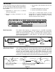
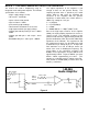
If you do not have an audio generator and an
oscilloscope, skip this test. Make sure that the
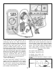
power is OFF and connect the audio generator and
the oscilloscope as shown in Figure 11 (replace the
multimeter leads with scope leads). Set the
generator to 400Hz minimum output and set the
oscilloscope to read 1V/div. Put the volume control
in the fully clockwise position. Turn the power ON
and set the audio generator output until a waveform
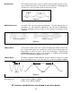
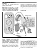
similar to the one shown in Figure 12 is obtained.
The flat area indicates clipping. You may have to
adjust the oscilloscope time base for correct
comparison. Measure the peak to peak voltage at
which the clipping first occurs and record here:
Peak to Peak Reading = __________________
The power output before clipping is equal to the
square of the rms voltage across the speaker
divided by the speaker impedance. The rms voltage
for a sine wave is equal to the peak voltage times
0.707. To get the peak voltage, divide the peak to
peak reading recorded above by 2.
Multiply the peak by 0.707 and square the result.
Divide by 8Ω (speaker impedance) to obtain the
maximum power output before clipping distortion
occurs. Maximum power output should be 1/2W or
greater. If this test fails, replace the battery with a
power supply capable of delivering 1/2A @ 9V or
replace the battery with a fresh alkaline battery.
Example
If the peak to peak voltage - 5.66
Peak Voltage - 5.66 x 0.5 or 2.83
rms Voltage - 2.83 x 0.707 = 2.0
rms Voltage Squared - 2 x 2 = 4
Dividing by speaker impedance of 8Ω gives a power
of 0.5W.
Figure 12
Peak to Peak
Flat Area
Figure 11
V
20A
A
COM
V
ΩΩ
9V Battery
-9-
455kHz