
Instruction manual

-4-
The audio in this radio is amplified by using an
integrated circuit audio power amplifier. The LM-386
specifications are as follows:
• Single supply voltage (4-12V)
• Idle current - 4 milliamps
• Inputs referenced to ground
• Input resistance - 50kΩ
• Self-centering output voltage
• Total harmonic distortion less than 0.2%
• Output power with 9 volt supply voltage
• Voltage gain with 10µF from pin 1 to 8 - 200 or
46dB
• Voltage gain with pins 1 and 8 open - 20 or
26dB
• Bandwidth with pins 1 and 8 open - 300kHz
The output impedance of the amplifier is low
enough to drive an 8Ω speaker directly. The
coupling capacitor value is picked to pass audio
signals down to 100 cycles by matching the
reactance of the capacitor with the speaker
impedance. In other words, 8Ω = 1/2πfC, where f =
100Hz. By solving for C we get:
C = 1/(2πf)(8Ω)
C = 1/(6.28)(100)(8)
C = 1/5026
C = 0.00019896 or C ≈ 200µF (220µF used)
Due to the high input resistance of the amplifier
(50kΩ), the audio coupling capacitor C3 can be as
small as 0.1µF. The equivalent resistance at the
junction of R8 and VR3 is approximately 6.6kΩ (the
parallel combination of R8, VR3 and the 50kΩ input
impedance of the LM-386). The capacitor C2 and
this equivalent resistance sets the 3dB corner used
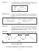
to attenuate any IF voltage at pin 13. A simple RC
filter attenuates at a rate of 6dB per octave (an
octave is the same as doubling the frequency). By
using 6.6kΩ as the equivalent resistance and
0.005µF as the capacitance, we get a 3dB corner at
approximately 4.8kHz. To get to 455kHz, you must
double 4.8kHz approximately 6.6 times. This
equates to a reduction of the IF voltage at the R8 -
VR3 junction of 39.6dB (6dB per octave times 6.6
octaves), or 95 times.
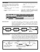
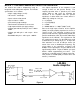
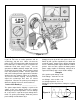
BLOCK 1 - THE AUDIO AMPLIFIER THEORY OR OPERATION
Figure 6
R12 = 1kΩ
LM-386
Audio Amplifier
R8 = 8.2kΩ
8Ω
C2 = 0.005µF
Pin 11
Carrier
Detect
Pin 13
Detector
Output
VR3 = 100kΩ
C3 = 0.1µF
C1 = 220µF