
Instruction manual
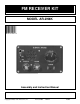
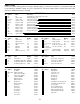
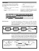
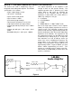
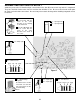
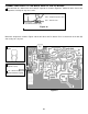
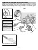
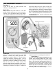

Figure 7
ASSEMBLY INSTRUCTIONS FOR BLOCK 1
Solder the parts to the PC board and put a check mark in the box (!) next to each step after it is completed.
The parts should be similar to the sketch in each box, but will differ in size. Be sure to check each solder point
for shorts and cold solder connections. Be careful to prevent static discharge when handling integrated circuits
U2 and U3.
-5-
C3 - .1µF Capacitor
C4 - .1µF Capacitor
104
Insert the IC socket into
the PC board with the
notch in the same
direction as the marking
on the PC board.
Insert the LM-386 IC into
the IC socket with the
notch in the same
direction as the notch on
the socket.
Notch
PC Board
Marking
C15 - 220µF Lytic
Polarity
Mark
(–) (+)
C14 - 4.7µF Lytic
C21 - 4.7µF Lytic
Polarity
Mark
(–) (+)
U3 - 78L05 Voltage
Regulator
Bend the leads as shown
and make sure that the
flat side matches the PC
board marking.
Flat Side
R8 - 8.2kΩ Resistor
(gray - red - red - gold)
R12 - 1kΩ Resistor
(brown - black - red - gold)