
Instruction manual

-7-
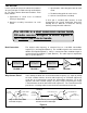
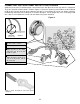
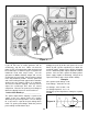
CONNECTING THE FRONT PANEL PARTS TO THE PC BOARD
Solder the parts to the PC board and put a check mark in the box (!) next to each step after it is completed.
The parts should be similar to what is shown in Figure 9. To wire the speaker, pot and switch, cut the indicated
length of wire from the roll of 22 gauge solid wire and strip 1/4” of insulation off of each end. Before soldering,
mechanically connect the wire to the parts as shown in the figure. For the jumper wire, cut 2” of 22 gauge solid
wire, strip 1/4” of insulation off of each end and solder to the points indicated.
Speaker Leads - 4” wires
Battery Snap
ON/OFF Switch
Attach the wires to the switch
and points A & B on the PC
board as shown.
VR3 - 100kΩ Volume Control
Attach the wires to points C, D,
& E on the PC board. Cut off
tab on the pot.
Jumper Wire (temporary)
Incorrect
(Lead too long)
Correct
Figure 9
+
_
Make a good mechanical connection before
soldering.
Tab
3”
4”