
Instruction manual

-8-
TEST PROCEDURE - BLOCK 1
Procedure 1
If you do not have an audio generator and
multimeter, skip to procedure 2.
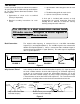
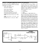
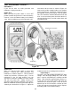
Power Test
Make sure that the power switch is in the OFF
position (handle away from the 2 wired terminals).
Connect a fresh 9V alkaline battery to the battery
snap. Set the multimeter to read on the 20V scale
and connect to the circuit as shown in Figure 10.
Connect the positive voltage probe to the positive
lead of capacitor C4. Connect the common probe to
the negative lead from the battery. Turn the power
ON. The multimeter should read between 4.5V and
5.5V. If not, turn off the power and check that U3 is
correctly installed. Also, check for solder shorts and
unsoldered leads.
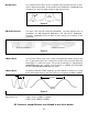
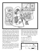
Audio Gain
Make sure that the power switch is in the OFF
position. Connect the audio generator and
multimeter as shown in Figure 11. Turn the volume
control fully clockwise (maximum gain). Put the
multimeter in the AC 20V position, turn the
generator to minimum at 400Hz sine wave output,
and turn the power ON. Slowly increase the
generator output until the multimeter reads 2Vrms.
Move the multimeter lead to the generator output as
shown by the dashed lines in Figure 11. Adjust the
multimeter for the best reading and record here:
Input Voltage = ___________________
The gain is the output voltage divided by the input
voltage. Since the output voltage was set at 2V, the
gain is equal to 2 divided by the reading recorded
above. Gain should be approximately equal to 17.
If gain test fails, turn off the power and check the
connections on all external parts. Check for shorts
between pins on IC U2 and make sure that all of the
IC pins are properly inserted in the socket. Replace
the battery with a fresh alkaline battery.
Figure 10
V
20A
A
COM
V
ΩΩ
9V Battery
Temporary Connection