
Installation manual


P12V
P5V
DATA 0
DATA 1
LED
COM P12V
P5V
DATA 0
DATA 1
LED
COM
J1J2
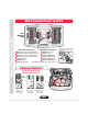
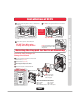
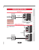
Wire Connections to EL25
Wire Connections to EL25
Wire Connections to EL25
Optional Modules
Note: All relays are factory set to “Strike” and “10 sec.”
O
f
f
O
f
f
On
On
On
Off
O
f
f
O
f
f
On
Off
Off
13
12
11
10
4
3
2
1
5
8
9
6
7
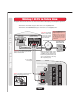
20-Pin Input
to Main Board
14-Pin Output
to Main Board
Ground
Output Board
Input Board
Back
Mounting
Plate
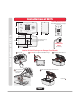
Optional Module Mounting Positions
RG-6 Coaxial
Connector
RG-59u
Coaxial
Connector
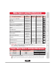
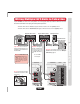
Input Board Connections Output Board Connections
Door 1 Exit Request and Door Status
Door 2 Exit Request and Door Status
Door 3 Exit Request and Door Status
Door 4 Exit Request and Door Status
Postal Lock Input
AutoCall Input
Power 12 VAC Input
Resident Tip / Ring
Telco Tip / Ring
Relay 4, NO,NC,COM
Relay 3, NO,NC,COM
Relay 2, NO,NC,COM
Relay 1, NO,NC,COM
Caution! A Static Discharge
can Damage Circuit Boards
1
2
3
4
5
6
8
9
10
11
12
13
7
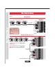
Do Not overload the removable
terminal block connectors. One
wire per hole.
Main
Circuit
Board
CCTV
J400
Optional CCTV
Module (Page 15)
(Replaces Call
Button Board)
Optional RF
Module (Page 14)
(Fits in J400
and/or J407)
Optional Wiegand
Module (Page 14)
(Fits in J400
and/or J407)
J407
Page 2