
Installation manual


Installation of EL25
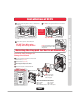
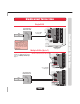
Rotating the Keypad for Vertical Mounting
Installation of EL25
Installation of EL25
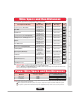
O
f
f
O
f
f
On
On
On
Off
O
f
f
O
f
f
On
Off
Off
1
1
2
3
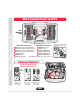
Disconnect all Plugs from Main Circuit Board and
Remove Board. (4 Screws)
2
Remove Bracket. (4 Screws)
3
Rotate Keypad 90 Degrees Clockwise.
4
Reverse the Sequence to Reassemble Unit.
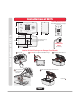
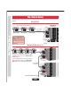
6
Secure Back Mounting Plate to Surface or Pedestal Post
in 4 Places.
Reverse the Sequence to Reassemble Unit.
Bracket
Keypad
Main Circuit Board
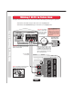
Main Circuit Board Connections
J200 - Speaker
J402 - Light
J404 - Call Button Board
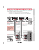
7
8
Run
All
Wires Through Conduit Hole for Connections.
EL25
MUST
be Properly
Grounded!
See Page 16.
Keep Wires Neat!
Use zip ties if necessary.
DO NOT Pinch Wires when
Closing and Locking the Unit!
Caution! A Static Discharge can
Damage Circuit Boards
ONLY Vertical
Mounting Position
Do Not overload the removable
terminal block connectors. One
wire per hole.
J401 - Keypad
J406 - Light
J201 - Microphone
Note: Bracket notch
lines up with ribbon
cable on keypad.
Page 5