
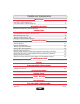
Installation manual

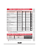
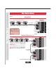

Relay 4
Com
NC
NO
Relay 3
Com
NC
NO
Relay 2
Com
NC
NO
Relay 1
Com
NC
NO
Resident
Telco
Tip
Ring
Tip
Ring
8
9
10
11
12
13
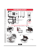
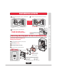
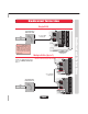
Wiring 1 EL25 to Telco Line
Wiring a Single EL25
The bypass board allows the EL25 to be disconnected without interrupting normal telephone operation.
Wiring a Single EL25
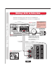
OPERATE BYPASS
Ring
HOME
Tip Ring
TELCO
Tip
SYSTEM
Bypass Board
(Mount in the House)
(NOT Provided)
Ring
Tip Ring
Tip
Home Phone
Alarm System Position
Use 18-24 AWG
2 twisted pair
Important: The Voltmeter measurement
between the Tip and Ring should read
between 48 and 53 VDC.
Note: If the EL25 unit will be used in
conjunction with an alarm system,
you
must
connect the telephone line
to the alarm system first. If the units
are not connected in this order, they
will not operate properly.
4
4 3 2 1
3
2
1
When the EL25 unit is
in use
, the bypass switch must be set to the
operate
position.
When the EL25 unit is
disconnected
, the bypass switch must be set to the
bypass
position.
•
•
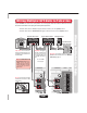
Output Board
(See page 2)
Telco Entrance Box
Demarcation Point
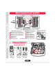
Do Not overload the removable terminal
block connectors. One wire per hole.
Important: The Bypass
Board (located inside
the property) allows
access to the phone in
case the EL25 fails.
Never
run
Data wires
and
High Voltage wires
in the
same
conduit. The high
voltage wires may interfere
with the data wires, possibly
causing the system to
malfunction.
Page 6