
Owner`s manual


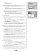


System Overview
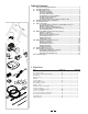
• Components included with your Travel Trac
™
RealAxiom shown in black.
• Owner supplied components shown in grey.
II. System Requirements
• PC: Pentium 3 or better
• Operating system: Windows 2000, Windows NT or Windows XP
• Hard disk: 10GB of free disc space / 7200 RPM
• RAM: 256MB
• Monitor: 800 X 600
• Port: USB
• DVD Drive
III. Assembly
Note: All references to Left and Right are from the rider’s perspective.
A. Trainer Assembly
1. Remove the trainer base, resistance unit and all parts from the box. If you
believe parts are missing, please contact our Technical Support department
for assistance at 1-800-553-8324.
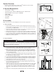
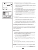
2. Attach the rubber feet (E) to the trainer base (A) by pressing them into the
ends of the trainer base frame tubes. See Figure 3.
3. Attach the handle (F) to the end of the axle support bolt that protrudes from
the trainer base. Align the “D” shaped end of the bolt with the corresponding
recess inside the handle, and tap the handle lightly into place. See Figure 3.
4. Attach the resistance unit (B) to the mounting plate (C) using 2 M5 bolts and
washers as shown in Figure 4.
B. Bicycle Installation
1. Place the trainer base on a flat, stable surface near your computer so that
you’ll have a clear view of the monitor when seated on the bike.
2. Note: Replace the bicycle’s rear wheel quick release (QR) skewer with the
one provided with the trainer. See bicycle owner’s manual for instructions
on how to properly adjust the QR skewer. Make sure the QR skewer is tight
and not damaged or bent.
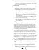
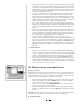
3. Loosen the locking ring (G) by sliding it all the way to the right until it contacts
the handle (F). See Figure 5. Spin the handle counterclockwise to fully loosen
the right side axle support cup (H).
4. Loosen the knob bolt (D) by turning it counterclockwise so that the resistance
unit is as close to the floor as possible (to provide clearance for the rear wheel).
5. Lift the bicycle into position, so that the rear QR skewer is aligned with the
right and left axle support cups (H). See Figure 6.
6. Fit the QR skewer lever on the left side of the wheel into the left axle sup-
port cup. Rotate the support cup as necessary, until the notch in the cup is
aligned with the QR skewer lever.
7. Tighten the right side axle support cup against the QR skewer nut on the right
side of the wheel by spinning the handle clockwise until it contacts the QR
skewer nut. Once contact is made, tighten the handle an additional
1
/
4
to
1
/
2
rotation, until the QR skewer is firmly clamped between both axle support
cups.
8. Tighten the locking ring (G) by sliding it all the way to the left (toward the
3
3
2
Monitor
PC
I
K
L
P
N
B
O
A
4
6
F
H
H
5
UNLOCKED
LOCKED
F
H
G
E
F
Read and follow all instructions concerning installation of the bicycle on the trainer.
Failure to securely attach the bicycle to the trainer could result in the bicycle falling,
causing injury to the rider or bystanders.
! WARNING
B
D
C