
Owner`s manual


bike). See Figure 5.
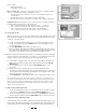
9. Check that the bicycle is securely installed in the trainer by pushing or pull-
ing on the bicycle’s top tube or seat.
10. If the bicycle is not secure, check to see that the QR skewer lever and nut
are properly positioned in the axle support cups, and that the right side axle
support cup is securely tightened.
11. It is important to maintain the correct pressure between the tire and the drive
roller. Tighten the Knob Bolt (D) until the drive roller touches the tire. Then
turn the Knob Bolt an additional three complete rotations. If the tire slips
during use, tighten the bolt by additional
1
⁄2 turns to eliminate the slippage.
C. SofTrac Polyurethane Drive Roller
The unique SofTrac drive roller on the RealAxiom is made of durable polyure-
thane, which significantly reduces tire noise and tire wear while increasing trac-
tion between the tire and roller (less tire slippage). There are a few important
points to keep in mind about the SofTrac roller.
1. To avoid damaging the roller, DO NOT apply the rear brake while using the
trainer. Locking the rear wheel at high speed can seriously damage the poly-
urethane roller.
2. Allowing the tire to slip against the roller will also accelerate roller wear.
Maintain sufficient pressure between the tire and the drive roller to prevent
slipping. During installation, tighten the Knob Bolt (D) until the drive roller
touches the tire. Then turn the Knob Bolt an additional three complete rota-
tions. If the tire slips during use, tighten the bolt by additional
1
⁄2 turns to
eliminate slippage.
3. Pedaling with a smoother stroke and applying power more evenly when
accelerating will also help prevent the tire from slipping.
4. Use a smooth tread tire at least 23mm in width.
5. Maintain the recommended maximum inflation pressure for your tire.
6. Over time the SofTrac roller may show some slight signs of wear. This is
normal, and does not affect the performance of the roller.
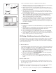
D. Handlebar Console Installation
1. Attach the console to the handlebar as shown in Figure 7. Open the quick
release bracket and install on the handlebar, preferably close to the stem.
For use on larger diameter handlebars, it may be necessary to remove the
two rubber shims (J) from the bracket.
2. Spin the quick release lever to adjust bracket clamping tension, and then flip
the quick release lever upward to secure the bracket in place.
3. If the bracket clamping tension is too loose or too tight, open the quick
release lever, adjust clamping tension, close the lever and re-check for
secure attachment.
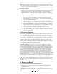
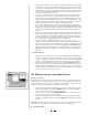
E. Cadence Kit Installation
The cadence kit consists of a magnet (attached to the crank arm) and a sensor
(attached to the left chainstay), which counts the number of pedal revolutions
per minute.
1. Loosely attach the sensor (K) to the outside of the left (non-drive side) chain
stay using two zip-ties (R). See Figure 8.
4
7
Failure to securely attach the bicycle to the trainer could result in serious injury.
! WARNING
To avoid damaging roller, DO NOT apply rear brake while roller is spinning.
CAUTION
R
R
K
L
Q
8
Q
L
9
L
10