
User's Manual


Page 2 ELK-6030 PIR Installation Manual
INSTALLATION
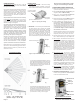
1. OPENING THE HOUSING - Remove the locking
screw along the bottom (if installed). Push in the
retainer tab and lift the front away from the backplate.
2. MOUNTING - To mount directly onto a wall WITHOUT
the swivel bracket, start by inserting the supplied
blanking plug into bracket mounting hole. This is very
important! See Figure 3. Next, locate the 9 dimple
marks on the inside of the backplate. Choose 2 (or
more) of these for use as the screw mounting holes.
Drill out the necessary holes using 1/8" bit. To
prevent air or contaminants from getting into the
sensor, DO NOT leave any exposed or unused holes!
To mount with the supplied Swivel Bracket, start by
attaching the bracket's base to the wall in the chosen
location. Next, fit the backplate over the bracket and
install the locking disc and small screw provided. Do
not tighten this screw until the angle and direction
have been adjusted as required.
Sensor must be enrolled into the control
using one of the following two methods.
3. SENSOR ENROLLMENT FROM KEYPAD
3.1 Make sure the M1XRFTW Transceiver is powered
up and enrolled with the M1 Control.
3.2 Enter M1 Keypad Installer Programming and
navigate to Menu: 14-Wireless Setup
3.3 Scroll up to sub-menu:3:Learn Sel Wireless
Transmtr and press Select (right arrow).
3.4 Scroll to and select an unassigned WZone (wireless
zone) and press Learn (right arrow) to enroll.
3.5 Insert the Batteries into the 6030 as soon as the
keypad displays: Push Transmitter Button. The
M1G will speak; “Press transmitter button for zone
xx”. If successful the Keypad will chime and briefly
display the 6 digit TXID code of the sensor. If a TXID
is not displayed then enrollment was not success-
ful. Should this happen, remove the batteries,
wait 5 seconds, and re-insert.
Rapid-Enroll will auto advance to the next wireless
zone in sequence and wait for the next sensor.
Repeat the previous step for each new sensor.
3.6 After all wireless sensors are enrolled, press the
ELK or Select Wireless key to stop Rapid-Enroll.
3.7
Set the Loop ID. This sets which sensor input is to
be assigned to the wireless zone, allowing multi-
input sensors to be used. Since the 6030 Sensor
is a single input device it will always identify itself
as Loop "2". The M1 default for all wireless zones
is Loop "0". Change this by scrolling to the wireless
zone and pressing the HW (left arrow) button. An
8 digit number (the TXID in decimal) will now display
followed by Loop = 0. Move the cursor to the right
(press RIGHT arrow) and enter a "2". Press the ELK
key or the Select Wireless key to back out.
3.8 Set Supervision Type - Set this to "1" (Normal
Supervision). This informs the control to expect a
supervisory check-in report from the 6030 Sensor
approximately every 64 minutes. A separate M1
option sets the number of missed check-ins that will
be allowed before a sensor is declared missing. To
view/change the supervisory type press the ELK
or the Select Wireless key to locate Sub-Menu:
2:Xmit Transmitter Opt. Scroll to the desired
wireless zone, press Select (right arrow) and scroll
to Option 2: Supervision Type. If set to "0" the
control will not expect a supervisory check-in.
3.8 PIR Auto Restore - Do Not Enable. The 6030 PIR
will transmit a restore after each alarm. This option
is included in the M1 to support other brands of
wireless PIRs that do not transmit restorals.
3.9 PROGRAM THE ZONE DEFINITION - This must
be done from Keypad Menu 5 - Zone Definitions
for all new enrolled wireless zones.
GUIDELINES FOR USE
The 6030 Sensor is for indoor use only. It may be
mounted directly on a wall or in a corner, with or without
the supplied swivel bracket.
It is recommended that the ELK-6030 be located within
100 feet of the control/transceiver. While an open-air
range of 400 feet or more is possible, adverse indoor
and environmental conditions can significantly reduce
the actual transmission range. Small changes to the
sensor's mounting can often make a big difference in
transmission range.
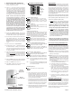
Always locate the sensor where an intruder is most likely
to walk
across the coverage pattern. Aim the sensor
so that it faces inward toward a solid reference point
such as a wall. Corner mounting often provides the best
detection coverage. See Figure 1.
Choose the location and mounting height carefully. For
optimum performance the recommended mounting
height should be 6 1/2 to 7 1/2 ft. The surface must be
solid and free of any noticeable vibrations. As with all
PIR sensors, select a location that avoids direct
sunlight, glass windows, fireplaces, heating or cooling
sources, and areas of high humidity. Always ensure the
sensor has a clear line of sight of the area to be
protected. Understand that infra-red energy does not
pass through solid objects, including glass.
DO NOT mount a wireless sensor near metal duct work
or other large metallic surfaces that might shield or
adversely affect the RF signals. Prior to permanent
mounting, we recommended a walk test be performed
with the control/transceiver to verify acceptable
operation of the wireless sensor at its intended location.
Motion Sensors are not recommended for areas where
a pet can roam. Pets can and will trigger a motion sensor.
Windows should be closed in any area which has an
armed motion sensor.
NOTE: A deluxe 90° swivel bracket may be purchased
and used in lieu of the standard swivel bracket. The
deluxe bracket has a short extended arm and allows
the sensor to be aimed at up to a 90° offset from the
wall or base. This bracket also allows the sensor to be
drop mounted from a ceiling. Refer to page 4.
COVERAGE PATTERNS
(2) Push in on retainer tab
(3) Lift here
to separate
Figure 2. Opening the Housing
(1) Remove locking
screw (if installed)
Tamper Switch
2 x CR123A Lithium
Batteries
Option Switches
Figure 5. Back View of Sensor
Battery #2
Battery #1
Figure 3. Prep for Wall Mounting (No Bracket)
Blanking Plug
Bracket mounting hole
Backplate
Figure 4. Standard Swivel Mounting
Swivel Bracket
Locking
Disc
Backplate
Figure 1. Top and Side Views
(assumes range is set to "HI")