
User's Manual


Page 4 ELK-6030 PIR Installation Manual
LIMITATIONS
While the 6030 Passive Infrared (PIR) Motion Detector
is a highly reliable intrusion detection device, it does not
offer guaranteed protection against burglary. Any
intrusion detection device is subject to compromise or
failure to warn for a variety of reasons:
PIR Detectors can only detect movement within a
specific coverage area as diagrammed in this manual.
To detect movement, the PIR Detector senses the
infrared energy that is emitted from an intruder moving
across the sensor's field of view.
PIR Detectors do not provide volumetric area protection.
They create multiple beams of protection. Intrusion can
only be detected in unobstructed areas covered by
those beams.
PIR Detectors cannot detect motion or intrusion that
takes place behind walls, ceilings, floors, closed doors,
glass partitions, glass doors, or windows.
The radio transceiver only provides communications.
It does not have anything to do with detecting motion.
LIMITED WARRANTY
The 6030 Wireless PIR Sensor is warranted to be free
from defects and workmanship for a period of 2 years
from date of manufacture. Batteries used with wireless
devices are not warranted. Elk makes no warranty,
express or implied, including that of merchantability or
fitness for any particular purpose with regard to batteries
used with wireless devices. Refer to Elk’s website for
full warranty statement and details.
PO Box 100 3266 US Hwy 70 West
Hildebran, NC 28637
828-397-4200 828-397-4415 Fax http://www.elkproducts.com
Printed in USA
L645 Rev. A 11/19/12
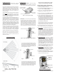
A deluxe 90° swivel bracket may be purchased and used
in lieu of the standard swivel bracket. This bracket has
a short extended arm and allows the sensor to be aimed
at up to a 90° offset from the wall or base. This bracket
also allows the sensor to be drop mounted from a ceiling.
OPTIONAL DELUXE 90° SWIVEL MOUNT
ANTI-TAMPER SWITCH
This switch detects the separation of the front housing
from the backplate. When this is tripped a signal is
transmitted to the control/transceiver, causing the
associated zone to become violated. Snapping the front
housing back onto the backplate transmits a restoral.
Note: Tamper can be ignored for any sensor (zone)
by setting its Zone Type to 1=Normally Closed.
FUNCTIONAL 'SYSTEM' TESTING
A system test should be done by physically walking
across the 6030 coverage pattern while the system is
fully armed. NOTE: Allow time for the Sleep Cycle Timer
to expire before testing. Always notify the Central
Monitoring Station prior to performing any testing.
BATTERIES
The 6030 battery compartment holds 2 x CR123A Lithium
batteries. The estimated service life of these batteries
is 5 to 7 years in typical residential usage with the Sleep
Cycle set to LG (Long),
Battery #1 (lower) is supervised for low voltage. When
the sensor detects the voltage has reached 2.6 VDC or
less (under load), a Sensor Low Battery trouble will be
transmitted to the control/transceiver. This trouble will
be attached to all future transmissions until fresh new
batteries are installed. Battery #1 is the primary power
source for all critical functions (motion detect and radio
transmission) of the 6030 sensor.
Battery #2 (upper) is not-supervised for low voltage.
This battery is a secondary (reserve) power source for
the 6030 critical functions, but it is the primary (sole)
power source for the White Security/Convenience LED.
The White Security/Convenience LED will not operate
without a good battery installed in Battery #2 location.
We strongly recommend installing a battery in both
locations. These 2 batteries are electrically isolated in
such a way that critical functions of the 6030 can draw
power either battery, but the White Convenience LED
can only draw power from Battery #2.
To clear a sensor low battery trouble condition, install
new batteries and then trip the sensor a couple of times.
This clears the low battery trouble and sends "all good"
to the control/transceiver.
Caution: Excessive use of the White Security/
Convenience LED will rapidly reduce the life of
Battery #2. More importantly, because the 6030
sensor is able to tap into Battery #2 for secondary
power, any reduction of its life naturally reduces
the overall operational life of the sensor. If maximum
sensor operational life is the top priority, the
Security/Convenience LED may be disabled by
turning DIP Switch #3 OFF.
BATTERY REPLACEMENT
Use only CR123A 3V Lithiums. Replace both batteries
at the same time. If possible, both batteries should
have the same manufactured date code. Replacements
can be obtained from Alarm Distributors.
1. Remove sensor from back housing.
2. Observe correct polarity when installing the new
batteries. Do not bend or damage the metal battery
holder contacts. Approved Batteries: 3V Lithium -
Panasonic CR123A, Duracell DL123A, Varta CR123A,
Sanyo CR123A
3. Re-test sensor operation with the control.
BATTERY WARNING: Risk of fire, explosion
and burns. Do not attempt to recharge or
disassemble. Do not incinerate or expose to
heat above 212° F (100° C). Dispose of used
batteries properly. Keep away from children.
ACTIVATING THE WHITE
SECURITY/CONVENIENCE LIGHT
TM
This high-intensity LED projects light out the front of the
sensor. There are five (5) modes of operation: 1)Flash
during an audible alarm activation. 2)On Solid when
motion is detected and either the control is armed AWAY
mode or when output 4 is On. 3) Flash on command from
control. 4)On Solid by command from control. 5)Quick
blip in walk test mode when motion is detected.
Note: For all conditions EXCEPT Walk Test, the
white LED may be totally disabled by DIP Switch #3.
1) Flash upon audible alarm activation
If DIP Switch #3 is ON,
ANY audible alarm activation
from the Control (not Silent 24hr Police) will cause the
White LED to flash. This flash will continue until either
the Alarm Cutoff timer expires, the Control is disarmed,
or Battery #2 (the upper battery) is drained.
Note: The 6030 reacts to two-way wireless commands
from the M1 Control. Please understand that it can
take several seconds for the 6030 to receive a
command. The time delay is typically 8 seconds or
less. Be prepared for this delay during testing and
operation. Do not expect instantaneous reaction.
Activating the white LED via ElkRP Rules
The white LED may be controlled via ElkRP Rules using
M1 Outputs 4, 5, & 6. These outputs do not appear on
the M1 board and are generally only used as rule flags.
The 6030 detects the state of these 3 outputs and
performs as follows:
2) On Solid if Motion Detected while armed to Away
Any motion detected while the control is armed to AWAY
mode will result in the white LED turning On for approx.
18 seconds. {DIP Switch #3 must be ON}
OR
On Solid if Motion Detected and Output 4 is on
Any motion detected while M1 Output 4 is On will cause
the white LED to turn On for approx. 18 seconds.
Additional motion can restart this time. Output 4 can be
turned On at a specific time, date, or condition using an
ElkRP rule. E.G. "When Sunset - Then Turn Output 4
On." Use another ElkRP rule to turn Output 4 Off when
this LED action is no longer desired. E.G. "When Sunrise
- Then Turn Output 4 Off."
3) Flash - on command [M1 Output 5]
When the 6030 sees M1 Output 5 turn On it will start the
white LED flashing for approx. 18 seconds. Output 5
can be turned On at a specific time, date, or condition
using an ElkRP rule. E.G. "When 5:30PM (Close Time?)
- Then Turn Output 5 On for 15 seconds." (15 seconds
is an arbitrary value) The crucial point is that Output 5
must first be turned Off before it can again be turned
back On to restart the white LED Flash.
Solid On - on command [M1 Output 6]
When the 6030 sees M1 Output 6 turn On it will turn the
white LED On Solid for approx. 18 seconds. Output 6
can be turned On at specific time, date, or condtion
using an ElkRP rule. E.G. When Entry Delay Starts
- Then Turn Output 6 On for 15 seconds." (15 seconds
is an arbitrary value) The crucial point is that Output 6
must first be turned Off before it can be turned back
On to restart the white LED Solid On.
Examples of Rules for the Security/Convenience Light:
Whenever Sunset
Then Turn On Output 4 On.
Whenever Sunrise
Then Turn Off Output 4 Off.
Whenever Time is 6:00pm (e.g. dinner time)
Then Turn On Output 5 for 15 seconds.
Whenever Entry Delay Starts
Then Turn On Output 6 for 15 seconds.
NOTES: DIP Switch #3 allows each individual 6030
sensor to be excluded from the above operations.
FCC COMPLIANCE STATEMENT:
This device complies with Part 15 of the FCC Rules.
Operation is subject to the following two conditions:
(1) this device may not cause harmful interference,
and (2) this device must accept any interference
received, including interference that may cause
undesired operation.
Part # Description FCC ID #
ELK-6030 Wireless PIR Sensor TMA ELK-6030
NOTE: ELK PRODUCTS IS NOT RESPONSIBLE
FOR ANY CHANGES OR MODIFICATIONS NOT
EXPRESSLY APPROVED BY THE PARTY
RESPONSIBLE FOR COMPLIANCE. SUCH
MODIFICATIONS COULD VOID THE USER’S
AUTHORITY TO OPERATE THE EQUIPMENT.
Backplate
Deluxe 90°
Swivel
Bracket
Locking
Disc
Figure 8. Deluxe 90° Swivel Bracket
(Separate purchase P/N: ELK-603022)