
User's Manual


Page 2 ELK-6040 Glass Break Installation Manual
1. GUIDELINES FOR USE
This sensor is a member of a reliable, high-quality product family using
the latest technology available. Please review the information in this
section to ensure you get the most out of the product.
The sensor must always be in direct line of sight of all windows to be
protected. It is not possible for the sensor to consistently detect breaking
glass around corners or in another room.
Wall mount
For wall mount applications the recommended location is on the wall
opposite (facing) the glass to be protected, provided that location does
not exceed the max. operating distance or line of sight criteria. In many
cases an adjoining perpendicular (90°) wall can be utilized. The orientation
of the sensor mounting (sideways, upside down, etc.) is not critical.
Ceiling mount
For ceiling mount applications be certain that the sensor has a direct line
of sight to the glass being protected. Since sound travels directionally
straight out from a broken window, a position of around 8 ft. (2.4 m) into
the room will provide the better detection.
Use the following guidelines to determine the best mounting location:
- Mount the sensor at least 3.3 ft. (1 m) from the windows being
protected and at least 4 ft. (1.2 m) from noise sources such as TVs,
speakers, sinks, and doors.
- Mount the sensor in the direct line of sight of the glass to be protected.
- Mount the sensor in a suitable environment: see specifications for
temperature and humidity ranges..
- Mount the sensor on a stable surface no greater than 25 ft. (7.6 m)
from the farthest point on the glass surface.
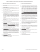
2. RECOMMENDED LOCATIONS AND OPERATING RANGE
The sensor is omni-directional, providing 360° coverage. Coverage range
is measured from the sensor to the point on the glass farthest from the
sensor. The sensor can be mounted as close as 3.3 ft. (1 m) from the
glass. The maximum range may vary depending on the type of glass being
protected:
- Plate, tempered, laminated, & wired glass - Mount sensor on
ceiling or the opposite/adjoining wall, maximum range is 25 ft. (7.6 m).
LOCATIONS TO AVOID
Improper location can affect the sensitive electronic components in this
product. To avoid causing damage to the product, to provide optimum
performance, and to prevent unnecessary nuisance alarms:
- Avoid rooms smaller than 10 x 10 ft. (3m x 3m).
- Avoid locations where lined, insulating, or sound-deadening drapes
or closed wooden shutters are used.
- Avoid mounting in the corner of a room.
- Do not install the sensor in humid rooms. Excess moisture on the circuit
board can eventually cause a short and a false alarm.
- Avoid locations that might expose the sensor to possible false alarm
sources such as:
- glass airlocks and vestibule areas
- kitchens and bathrooms
- corner mounting
- residential car garages
- small utility rooms
- stairwells
- small acoustically live rooms
- locations exposed to white noise, such as air compressors, etc.
It is recommended that the ELK-6040 be located within 100 feet of the M1
Control or M1XRFTW Transceiver. While an open-air range of 400 feet
or more is possible, adverse indoor and environmental conditions can
significantly reduce the actual transmission range. Small changes to the
sensor's mounting can often make a big difference in transmission range.
DO NOT mount a wireless sensor near metal duct work or other large
metallic surfaces that might shield or adversely affect the RF signals. Prior
to permanent mounting, we recommended a walk test be performed with
the control/transceiver to verify acceptable operation of the wireless
sensor at its intended location.
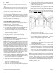
3. MOUNTING THE SENSOR
This product can be wall mounted or ceiling mounted.
1.1 Disconnect any alarm notification appliances, service related devices,
and extinguishing systems. Functionally test the sensor in its intended
location to verify the communications between it and the M1 Control.
It is very important to confirm that the sensor is within adequate range
of the M1 Control/Transceiver prior to permanently mounting.
Refer to Test Method #3 - Functional Test later in this guide.
- Hold the product in the intended mounting location or temporarily
mount it using some form of removable fastener.
- Confirm that the test signals from the sensor reach the control. If
no signal is received or if the RF signal is low, try relocating the
sensor to another location and retest.
1.2 After testing has been confirmed, mount the sensor and sensor base
as follows:
- Remove the screw located in the front.
- Remove the top cover by using a flat bladed tool in the screw
location to pry open the top cover.
- Locate the mounting location and drill holes in base per the
mounting impression in the base.
- Use the anchors and screws to secure the product to the
mounting surface.
1.3 Replace the product’s top cover:
- Snap the top onto the base.
- Replace the screw into the front location.
4. BASIC OPERATION
This product is equipped with an intuitive normal mode operation.
- In normal operation, the red LED will generally remain OFF.
- The wake up test will cause the red LED to illuminate two blinks.
- In response to an alarm the red LED will stay ON for approximately
4 seconds. The RF transmitter will send the alarm to the Control.
- In a trouble or maintenance required condition the red LED will not
illuminate in response to the wake up test.
- In a trouble condition such as low battery the sensor will send an
RF transmission to the Control.