
User's Manual


ELK-6040 Glass Break Installation Manual Page 3
5. INSTALLING / REPLACING BATTERY
The 6040 sensor uses a single CR123A Lithium battery. The estimated
service life is 5 years in a typical residential installation.
The Battery is supervised for low voltage. When the sensor detects the
voltage has reached 2.6 VDC or less (under load), a Sensor Low Battery
trouble will be transmitted to the control/transceiver. This trouble will be
attached to all future transmissions until fresh new batteries are installed.
When the Control indicates that it is time to replace the sensor battery,
remove the old battery and WAIT AT LEAST 20 seconds before installing
new battery. This time is necessary to clear and reset the low battery
condition from the sensor memory. After the new battery has been
installed, trip the sensor a couple of times. This should send an "all good"
to the Control and clear the low battery trouble.
Use only approved 3V Lithiums. Replacements can be obtained from any
local Alarm Distributor.
Note: Place the control panel into sensor test mode prior to replacing the
batteries. If the control panel is not in sensor test mode during battery
replacement, an alarm/tamper condition may be indicated.
1. Remove the product top cover.
2. Remove the old battery and properly dispose of it as recommended
by the battery manufacturer.
3. WAIT AT LEAST 20 SECONDS before installing new battery.
4. Observe correct polarity when installing the new battery. Insert
battery + to Red + sign next to battery well. Be careful not to bend
or damage the metal battery holder contacts.
5. Replace the top cover.
6. Replace the front screw.
7. Re-test sensor operation with the control.
Approved 3.0 Lithium Batteries are:
- Panasonic CR123A
- Duracell DL123A
- Varta CR123A.
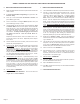
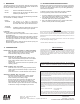
CR123
Lithium
Battery
Tamper
RF Ack
(Status)
ELK-6040
RF ACKNOWLEDGE LED
This bi-color LED IS located on the bare circuit board near the upper left
side. It provides visual confirmation of the two-way acknowledge
(response) from the control/transceiver and can only be viewed by
removing the sensor cover.
GREEN blink = Sensor successfully transmitted a violation (alarm) and
that signal was received and acknowledged by the transceiver. A
green blink is not provided for a sensor restore transmission..
ORG/RED blink = Sensor was not successful and did not get
acknowledged by the transceiver. POSSIBLE CAUSES: a) the Control
or M1XRFTW is powered off. b) the M1XRFTW is not enrolled with
control. c) the sensor is not enrolled. d) the distance between the
sensor and the transceiver is too great. Check the following:
A. Verify that the M1 Control is powered on.
B. Verify that the M1XRFTW Transceiver is powered on and that it is
enrolled with the M1.
C. Verify that the sensor is properly enrolled.
D. Trip another wireless sensor to see it can successfully communicate.
E. If above steps are OK, temporarily move the failed sensor closer
to the transceiver and retest. If sensor successfully communicates
at the closer range then it may be necessary to:
1. Relocate the transceiver to a closer and more central location to this
and all other sensors.
OR
2. Purchase and install an additional “remote” transceiver to cover the
area where this sensor was mounted.
TAMPER SWITCH
This switch detects the separation of the front housing from the backplate,
resulting in a signal being transmitted to the control/transceiver that will
cause the associated zone to become violated. Snapping the front housing
back onto the backplate will transmit a restoral.
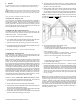
RF ACKnowledge LED
Cover Tamper Switch
Sensor Microphone
Lithium Battery
Alarm / Activity LED