
User's Manual
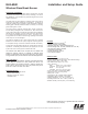


Page 4 ELK-6040 Glass Break Installation Manual
6. ENROLLING A SENSOR USING THE M1 KEYPAD
6.1 Make sure the M1XRFTW Transceiver is powered and enrolled with
the M1 Control.
6.2 Enter M1 Keypad Installer Programming and go to Menu: 14-
Wireless Setup
6.3 Scroll up to sub-menu:3:Learn Sel Wireless Transmtr and
press Select (right arrow).
6.4 Scroll to and select an unassigned WZone (wireless zone) and
press Learn (right arrow) to enroll.
6.5 Insert the Battery into the sensor when the keypad displays: Push
Transmitter Button and the M1G speaks; “Press transmitter
button for zone xx”). Upon successful enrollment the Keypad will
chime and briefly display the 6 digit TXID printed on the sensor. If
the TXID of the sensor does not display then enrollment was
unsuccessful. To attempt enrollment again you must remove
the battery and wait at least 20 seconds before re-
inserting.
Rapid-Enroll will auto advance to the next wireless zone in se-
quence and wait for a new sensor. Repeat the previous step for
each sensor.
6.6 After all wireless sensors are enrolled, press the ELK or Select
Wireless key to stop Rapid-Enroll.
6.7 Set the Loop ID. Scroll to each 6040 wireless zone and press the
HW (left arrow) button. An 8 digit number (TXID in decimal) will
display followed by Loop = 0. Move the cursor to the right (press
RIGHT arrow) and enter a "2" for the Loop ID . This is VERY
IMPORTANT! Press the ELK key to return back to the wireless zone
display. Loop ID informs the M1 how to handle the input transmission.
The 6040 Glass Break sensor MUST be set as Loop "2". NOTE:
The M1 default for all wireless zones is Loop "0".
6.8 Set Supervision Type - Set this to "1" (Normal Supervision). Press
the ELK or the Select Wireless key to locate Sub-Menu: 2:Xmit
Transmitter Opt. Scroll to the desired wireless zone and press
Select (right arrow). Scroll to Option 2: Supervision Type and set
it to "1". The control will now expect a supervisory check-in report
every 64 minutes. If set to "0" the control will not expect a
supervisory check-in from the sensor. NOTE: A separate M1 option
sets the number of missed supervisory check-ins before a sensor
is declared missing.
6.9 PIR Auto Restore - DISREGARD
6.10 PROGRAM THE ZONE DEFINITION - This must be done from
Keypad Menu 5 - Zone Definitions.
ENROLL SENSOR INTO THE CONTROL USING ONE OF THE TWO METHODS BELOW
7. ENROLLING A SENSOR USING ELKRP
7.1 Launch the ElkRP PC software and open the Customer Account file.
7.2 Click the "+" next to Zones (Inputs) to expand the view. Look for
any existing wireless zone groups. If there are none it will be
necessary to add or create a new group. To create a wireless
group, right click on Zones (Inputs) and click New Wireless
Zones. Place a check mark in the box to be added, starting with
Group 2. Click OK. Repeat if more wireless groups are required.
NOTE: The M1 Control requires all expanded zones to be defined
in groups of 16. E.G. Zones 17-32 = Group 2, zones 33-48 = Group
3, etc.
Since the first M1XRFTW Two-Way Transceiver must
always be enrolled at databus address 2 (the first expander),
this means that the first group of wireless sensors should be
defined as group 2. Since M1 allows a maximum of 144 wireless
zones, the last potential wireless zone can never be higher than
Zone 160. If a large number wireless zones is anticipated, it would
be a good idea to avoid conflict with any future Hardwired Zones
in the 17 to 160 range by NOT enrolling any Hardwired Zone
Expanders (M1XIN) at any data bus addresses below 10.
7.3 Double click on Wireless - Group _ (the group just added) and
double click one zone at a time to define the Zone Name, Definition,
Type, Attributes, etc.
4.4 The next step is to enter the sensor's TXID and the other wireless
setup data. This may be done directly from each zone definition
screen (click the Wireless Setup button) OR from the separate
Wireless Setup menu accessed from the folders column.
7.5 Place a check mark in the Enabled box.
7.6 Set Supervision type to "1" (Normal Supervision) for the 6040
Sensor. A setting of "0" means the control will not expect a
supervisory check-in from the sensor. For additional details refer
to Supervision on the previous page.
7.7 PIR Auto Restore - DISREGARD
7.8 Skip to the TXID box and enter the Sensor TXID that is printed on
the small label attached to the sensor.
7.9 Skip to the LOOP box and enter a 2.
7.10 Click Save. Repeat the entire step 4 for each additional Wireless
Zone and Sensor.
7.11 PROGRAM THE ZONE DEFINITION