
ELK Products Wireless PIR Motion Detector Installation


ELK-6030P PIR Installation Manual Page 3
6. After enrolling the sensor into the control and setting
the Option Switches, reposition sensor over the
back housing and snap it into place. This action will
activate the Walk Test mode for the next 10
minutes. Perform an immediate Walk Test accord-
ing to the procedure that follows.
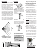
7. If the swivel mount bracket was used then it will be
possible to adjust (fine tune) the Sensor coverage.
If the swivel bracket was not used, and the sensor
was fixed mounted to the wall, the coverage pattern
is based on the mounting height and position.
8. After Walk Testing has been completed, secure the
sensor to the back housing using the locking screw
provided (small countersunk screw).
WALK TEST
Walk test is a way to verify that the sensor is operating
as desired and in the optimum location. Slow and short
steps should be taken across the coverage zones in both
directions. When motion is detected, the White LED
should blink once followed by a quick blink of the Green
RF ACK LED. The Green LED indicate that the sensor
transmitted an alarm signal an that the control/trans-
ceiver acknowledged that transmission. See paragraph
titled: RF ACKnowledge LED
NOTE: Walk Test mode bypasses the Sleep Cycle timer
allowing the Sec./Convenience LED and the RF ACK
LED to operate regardless of DIP switches 2, 3, and 4.
There are two Walk Test methods.
1. Sensor Walk Test - This is started by opening and
closing the sensor housing to violate the tamper
switch. Sensor Walk Test will end after 10 minutes.
NOTE: Sensor Walk Test can be forced to end by
either arming the M1 (any arm mode) or by
entering and exiting the System Walk Test mode.
2.
System Walk Test - This is started by activating
Keypad User Menu 3 - Walk Test Area. A wireless
command is sent to each enrolled 6030 PIR telling
it to join the System Walk Test mode. As each
sensor is tripped the keypad will chime and display
visual results. Press the asterisk (*) key to end this
walk test mode.
NOTE: Two-way commands are not immediate. It
can take several seconds for the sensor to receive
the command to enter or exit the walk test mode.
RF ACKnowledge (Green) LED
This LED is located in the clear lens on the sensor front.
It's a bi-color LED providing visual status of the two-way
acknowledge (response) from the control/transceiver.
In bright lighting conditions this LED may be difficult to
see. DIP Switch #2 allows the Green LED to be disabled
for all operations except the Walk Test Mode.
GREEN blink = Sensor has successfully transmitted
a violation (alarm) transmission to the transceiver
and that signal has been received and acknowledged
by the transceiver. The green blink is not provided
for a sensor restore transmission..
ORG/RED blink = Sensor was not successful in
transmitting after multiple attempts. POSSIBLE
CAUSES: a)Control or M1XRFTW is powered off.
b)M1XRFTW is not enrolled with control. c) Sensor
is not enrolled. d)Distance between the sensor and
the transceiver is too great. Check the following:
A. Verify that the M1 Control is powered on.
B. Verify that the M1XRFTW Transceiver is powered
on and that it is enrolled with the M1.
C. Verify that the sensor is properly enrolled.
D. Trip a different wireless sensor to determine if
it can successfully communicate.
E. If above steps are OK, temporarily move the
failed sensor closer to the transceiver and
retest. If sensor successfully communicates at
the closer range then it may be necessary to:
1. Relocate the transceiver to a closer and more
central location to this and all other sensors.
OR
2. Purchase and install an additional “remote”
transceiver to cover the area where this sensor
was mounted.
DISABLING RF ACKnowledge (Green) LED
DIP Switch #2 allows the RF ACKnowledge (Green) LED
to be disabled for regular operation, helping prevent
unauthorized persons from learning the coverage pat-
terns. It also helps extend battery life. Place DIP Switch
#2 in the "NO" position to disable the RF ACK LED, or
in the "YES" position to enable the RF ACK LED.
NOTES: DIP Switch #2 does not disable this LED from
working in the Walk Test Mode.
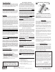
PULSE COUNT
RANGE
SLEEP CYCLE
SEC/CONV. LED
RF ACK. LED
- Future use -
ON OFF
Factory Default Settings Outlined in BOLD
6
5
4
2
3
1
3 - 4
1 - 2
HI
LO
SH
LG
YES
NO
NO
YES
N/A
N/A
PULSE COUNT (Switch 6)
Sensor must detect 1 or 2 events in the
coverage area before an alarm is created.
FUTURE (Switch 1)
Sensor must detect 3 or 4 events in the
coverage area before an alarm is created.
RANGE (Switch 5)
Sensor is set for the shorter detection range
(approximately 30ft.)
Sensor is set for the longest detection range
(approximately 40ft.)
To extend battery life, a mandatory sleep cycle (2 time
settings) begins after each alarm transmission. After
the Sleep Cycle expires, there must be ~8 seconds of
quiet (no movement) before the sensor will be allowed
to detect and send another radio transmission.
Long (120 secs.) Until this timer expires the
sensor cannot transmit another event.
SECURITY/CONVENIENCE LED (Switch 3)
This switch is not currently utilized.
Short (30 secs.) Until this timer expires the
sensor cannot transmit another event.
Sec/Convenience LED is NOT ENABLED
except for the Walk Test and audible alarms.
Sec/Convenience LED is ENABLED for
other functions other than Walk Test and
audible alarms. See back page for details.
RF ACK LED (Switch 2)
RF ACK (Green) LED is NOT ENABLED
except during the Walk Test Mode.
RF ACK (Green) LED is ENABLED, and
should blink Green upon a detect and positive
acknowledgment from the control.
3 - 4
1 - 2
LO
HI
LG
SH
NO
YES
N/A
SLEEP CYCLE (Switch 4)
YES
NO
4. SENSOR ENROLLMENT FROM ELKRP
4.1 Launch the ElkRP PC software and open the
desired Customer Account file.
4.2 Click the "+" next to Zones (Inputs) to expand the
view. Look to see if there are any existing wireless
zone groups. If there are none then it will be
necessary to add or create a new group. To create
a wireless group, right click on Zones (Inputs) and
click New Wireless Zones. Place a check mark
in the box to be added, starting with Group 2. Click
OK. Repeat if more wireless groups are required.
NOTE: The M1 Control requires all expanded zones
to be defined in groups of 16. E.G. Zones 17-32 =
Group 2, zones 33-48 = Group 3, etc.
Furthermore,
when an M1XRFTW Two-Way Transceiver is
included, it must always be enrolled at databus
address 2 (the first expander). This also means
that the first group of wireless sensors should be
defined as group 2. Since M1 allows a maximum
of 144 wireless zones, the last potential wireless
zone can never be higher than Zone 160. If a large
number wireless zones is anticipated, it would be
a good idea to avoid conflict with any future
Hardwired Zones in the 17 to 160 range by NOT
enrolling any Hardwired Zone Expanders (M1XIN) at
any data bus addresses below 10.
4.3 Double click on Wireless - Group _ (the group just
added) and double click one zone at a time to define
the Zone Name, Definition, Type, Attributes, etc.
4.4 The next step is to enter the sensor's TXID and the
other wireless setup data. This may be done
directly from each zone definition screen (click the
Wireless Setup button) OR from the separate
Wireless Setup menu accessed from the folders
column.
4.5 Place a check mark in the Enabled box.
4.6 Set Supervision type to "1" (Normal Supervision)
for the 6030 Sensor. A setting of "0" means the
control will not expect a supervisory check-in from
the sensor. For additional details refer to Supervision
on the previous page.
4.7 Skip the block titled: This device is a PIR (auto
restore). Do Not Enable. The 6030P PIR will
transmit a restore after each alarm as long as all
functions return to normal. This M1 option is for
other supported brands of wireless PIRs that do not
transmit restorals.
4.8 Skip to the TXID box and enter the Sensor TXID that
is printed on the small label attached to the sensor.
4.9 Skip to the LOOP box and enter a 2.
4.10 Click Save. Repeat the entire step 4 for each
additional Wireless Zone and Sensor.
5.
DIP SWITCH OPTION SETTINGS
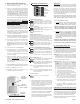
Green = Sensor transmitted and received a positive
ACK (acknowledgment) from the Control/
Transceiver.
Org/Red = Sensor attempted to transmit but did not
receive an ACK (acknowledgment) from the
Control/Transceiver.
Creep Zone
"Lookdown"
Security/
Convenience
LED (White)
RF ACK
Bi-Color LED
(Green + Org/Red)
Figure 6. Front View of Sensor
Figure 7. DIP Switches