ELK-M1XRFTW Two-Way Wireless Transceiver/ Expander for Elk Two-Way Wireless Sensors. Refer to page 8 for a listing of sensor part numbers. INSTALLATION MANUAL IMPORTANT NOTE: ELK-M1G and M1EZ8 Controls require application firmware ver. 5.2.10 or higher to be compatible with the M1XRFTW Receiver. Refer to Elk's website for "flash" file updates. For the very latest downloadable version of this manual please go to our website: http://www.elkproducts.com L644 Rev.
Table of Contents Installation and Setup ................................................................................................................... 4 Diagnostic LED Indicators ........................................................................................................................ 4 Setting the Data Bus Address and the Starting Wireless Zone ID ............................................................ 5 Data Bus Enrollment:: ........................................................
OVERVIEW The letters "TW" on the M1XRFTW signify "two-way", meaning this device is actually a transceiver rather than just a receiver. In other words, it has the ability to both transmit and receive. The compatible Elk 6000 series two-way wireless sensors are also two-way, making them vastly superior to traditional one-way wireless sensors.
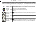
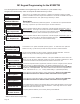
Installation and Setup INSTALL UNIT * SET ADDRESS AND OPTION JUMPERS * ACTIVATE M1 BUS ENROLLMENT PROCESS ANT1 On-board Antenna JP1 Bus Terminating Jumper ELK-M1XRFEG Data Bus Address Switches NOTE: ONLY addresses 2, 3, 4, or 5 should be used with the M1XRFTW. ELK-M1XRFTW Two-Way Transceiver RS-485 Data Bus Connections NOTE: Jumper JP1makes it convenient to terminate the RS-485 Data Bus if this is the last installed device. 1.
Setting the Data Bus Address and the Starting Wireless Zone ID The M1XRFTW "two-way" transceiver must be addressed and enrolled as the 1st zone expander (Data Bus Address # 2) on the M1 or M1EZ8 Control. For extended range and coverage up to 3 additional M1XRFTW transceivers may be installed. If installed these must be enrolled as the 2nd, 3rd, and 4th zone expander (Data Bus Addresses 3, 4, and 5) on the M1 or M1EZ8 Control.
Data Bus Enrollment:: Once the data bus address is set to "2" and the M1XRFTW has been powered up then it will be necessary to manually ENROLL the device in order for the M1 Control to recognize it. Data bus enrollment can be done from keypad programming "Menu 1 - Bus Module Enrollment" or from the ElkRP Remote Programming Software. (The steps below require an M1 LCD Keypad) 12345678901234567890123456 12345678901234567890123456 12345678901234567890123456 1.
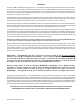
Operation How does the Elk Two-Way technology differ from one-way wireless technology? Elk's Two-Way technology is superior to traditional one-way wireless products in many ways. 1. Every signal sent by an Elk two-way sensor receives a positive acknowledgment from the transceiver. One-way systems have the reputation of being "fire and pray". 2. Elk two-way sensors only send one signal at a time.
Elk 6000 Series Wireless Sensors Enrollment and programming of wireless devices may be done from Keypad Installer Programming or from ElkRP Enrollment from Keypad Installer Programming utilizes Menu 14 and the LRN (Learn) method. The enroll method varies between sensors. Please follow the specific enroll method suggested below and read the additional programming recommendations.
'Quick Step' Enrollment of Elk 6000 Series Sensors Enrolling Sensors from the M1 Keypad Installer Programming (additional details on following pages) NOTE: The M1XRFTW must be enrolled on the data bus at address 2. 1. From M1 Keypad Installer Programming scroll or navigate to Menu: 14-Wireless Setup bPrgrr WirelessTransmtr 2. Press right arrow and scroll up to Sub-Menu: 3:Learn Selb 3. Press right arrow WZone and search of scroll to the first available (unused) location displaying TransmitrToLrn.
M1 Keypad Programming for the M1XRFTW From the keypad enter the Installer Level Programming mode. Press ELK, 9 > (enter installer code). Navigate to the Wireless Setup - Menu 14 and press the RIGHT arrow key to select.
123456789012345678901234567890121234 123456789012345678901234567890121234 123456789012345678901234567890121234 123456789012345678901234567890121234 123456789012345678901234567890121234 123456789012345678901234567890121234 123456789012345678901234567890121234 123456789012345678901234567890121234 123456789012345678901234567890121234 123456789012345678901234567890121234 123456789012345678901234567890121234 3:Learn Selb Prgr WirelessTransmtr 3a 123456789012345678901234567890121234 123456789012345678901234567
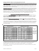
Appendix A - Data Bus Selection Table This table should help visualize how the Wireless Zones and Hardwired Zones share the data bus address assignments. Please note that No Wireless Zones Are Allowed Above Zone 160. This table shows the starting wireless Zone # and data bus address along with the additional data bus addresses and Zone #’s necessary to obtain the total and best mix of wireless and hardwired zones.
Appendix B - Examples of Zone Configurations Example A Example B Example C All 208 Zones as Hardwired 144 M1XRFTW Wireless Zones plus 16 Hardwired Zones 112 M1XRFTW Wireless Zones plus 48 Hardwired Zones Inputs on Main Panel Zones 1-16 Bus Addr N/A Inputs on Main Panel Zones 1-16 Bus Addr N/A Inputs on Main Panel Zones 17-32 Bus Addr 2 M1XIN Zones 17-32 Bus Addr 2 M1XRFTW Zones 17-32 Bus Addr 2 M1XRFTW Zones 33-48 Bus Addr 3 M1XIN Zones 33-48 Bus Addr 3 Optional 2nd M1XRFTW Zones
Appendix C - Installing Multiple Redundant M1XRFTW Transceivers After the first M1XRFTW Transceiver has been installed at address 2, up to 3 additional units may be installed for redundancy or improved coverage and range. Each addtional unit will require its own data bus address and must be enrolled into the control. IMPORTANT NOTE: There can be no more than 4 total ELK-M1XRFTW Transceivers connected to the M1 Control.
Appendix D - Updating Firmware in the ELK-M1XRFTW Operating firmware is stored in “Flash” memory. This allows electronic field updates and eliminates the old fashion method of changing IC chips or shipping boards back to the factory. As new firmware updates become available they will be posted on ELK's website. NOTE: Firmware updating can only be done through the M1 Control using a Direct to PC Com port connection or an optional Ethernet Network connection.
Page 16 M1XRFTW Installation Manual