
Installation manual


Page 4 M1XRFTW Installation Manual
Installation and Setup
1. Mounting - Two (2) #6 x 1/2" screws (not provided), one on each side of the housing should be used for mounting. The
receiver connects to the M1's Keypad data bus and may be remotely located up to several thousand feet away from the
control. DO NOT mount inside a metal enclosure or on metalized surface! Space at least 10 feet away from electrical
devices that generates noise, including the M1 Control. Electrical noise may negatively affect operation.
2. Wiring Connections - Turn the power Off on the Control Panel before making any wiring connections. Connect termi-
nals +12V, A, B, and Neg from the receiver to the M1's Keypad Data Bus (terminals +VKP, Data A, Data B, & Neg).
NOTE: Refer to the M1 Installation Manual and the M1DBH information in that manual about proper
connections of data bus devices with multiple homerun cables.
3. Antenna - The M1XRFTW uses a single on-board ceramic antenna. There is no external antenna re-
quired.
Diagnostic LED Indicators
There a four (4) LEDs on the board that provide valuable information as to the operation of the M1XRF:
STATUS (Data Bus Status) - Multiple conditions exist for this LED:
OFF = No Power to the M1XRF
ON Solid = Power is good but it is not yet enrolled with the M1 or the Microprocessor is not functioning.
BLINKING = 2 different blink rates:
- Slow "one blink per second" indicates Normal Operating mode.
- Two blips with a brief off time indicates unit is in Bootloader mode. It has not yet been flashed with the
application firmware. This should only occur if you are field updating the unit. It will not be operational
until application firmware has been flashed into the unit using ElkRP.
LEARNED RF - This LED will momentarily turn on when the M1XRF receives a valid transmitter and is in the process of
sending the signal packet back to the M1 Controller. As soon as the packet is acknowledged by the M1 Controller
the LED will turn Off.
ALL RF - This LED blinks whenever ANY Elk RF transmitter is detected.
DATA BUS ACTIVE - This LED blinks near continuously and indicates activity on the M1 Data Bus.
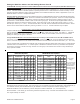
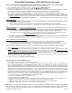
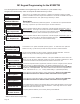
INSTALL UNIT * SET ADDRESS AND OPTION JUMPERS * ACTIVATE M1 BUS ENROLLMENT PROCESS
RS-485
Data Bus
Connections
Data Bus
Address Switches
NOTE: ONLY addresses
2, 3, 4, or 5 should be
used with the
M1XRFTW.
NOTE: Jumper JP1makes it convenient to terminate the RS-485 Data Bus if this is the last installed device.
ELK-M1XRFTW Two-Way Transceiver
ELK-M1XRFEG
JP1 Bus
Terminating
Jumper
ANT1
On-board
Antenna