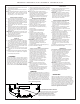
EZSTLDWS*1G EZSTL8WS*1G, 2G, 3G LZSTLDWS*1G LZSTL8WS*1G, 2G, 3G INSTALLATION & USE MANUAL Manual de instalación y uso Manuel d’installation et utilisation EZ ™ & LZ™ Series Versatile Bottle Filling Stations & Coolers EZ™ & LZ™ Serie versatil Botella Bombas y Enfriadores EZ™ & LZ™ Stations versatile de Remplissage de Bouteille Série et Refroidisseurs *Versatile Cooler Model LZSTL8WSLK alternate installations *Versatile Cooler Model LZSTL8WSLK configuration as shipped *Versatile cooler design allows uni
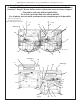
EZSTLDWS*1G EZSTL8WS*1G, 2G, 3G LZSTLDWS*1G LZSTL8WS*1G, 2G, 3G Note: Danger! Electric shock hazard. Disconnect power before servicing unit. Nota: peligro! Peligro de descarga eléctrica. Desconecte antes de reparar la unidad. Remarque : Danger ! Risque d'électrocution. Débrancher avant de réparer l'appareil. Pictured is unit only without bottle filler. En la foto, la unidad sólo sin relleno botella. Sur la photo, est une unité seulement sans remplissage de la bouteille.
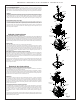
Fig. 2 Page 3 2" 51mm 7/8" 22mm 13 15/16" 354mm D (ALT.
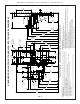
1000002243 (Rev. G - 08/19) Fig. 3 Page 4 F A (ALT. LOCATION) 3 7/8" 98mm 6 3/8" 162mm ‰ 7" 178mm D PREFERRED LOCATION 2" 51mm 7/8" 22mm 6 3/8" 162mm 17 7/8" 454mm ‰ 7" 178mm 5 3/4" 146mm 2" 51mm 6 3/8" 162mm FINISHED FLOOR D (ALT.
Page 5 A (ALT. LOCATION) 3 7/8" 98mm ‰ D PREFERRED LOCATION 2" 51mm 7/8" 22mm 6 3/8" 162mm 7" 178mm FINISHED FLOOR D (ALT.
1000002243 (Rev. G - 08/19) Fig. 5 Page 6 F 17 7/16" 443mm 13 15/16" 354mm D (ALT.
EZSTLDWS*1G EZSTL8WS*1G, 2G, 3G LZSTLDWS*1G HANGER BRACKETS INSTALLATION 1) Remove hanger brackets fastened to back of cooler by removing one (1) screw. 2) Mount the hanger brackets as shown in Figures 2, 3, 4 or 5. NOTE: Hanger Bracket MUST be supported securely. Add fixture support carrier if wall will not provide adequate support. Anchor hanger securely to wall using all six (6) 1/4 in. dia. mounting holes. INSTALLATION OF COOLER 3) Hang the cooler on the hanger bracket.
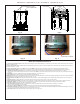
EZSTLDWS*1G EZSTL8WS*1G, 2G, 3G LZSTLDWS*1G LZSTL8WS*1G, 2G, 3G Service Instructions 11 Lower and Upper Shroud To access the refrigeration system and plumbing connections, remove four screws from bottom of cooler to remove the lower shroud.
EZSTLDWS*1G EZSTL8WS*1G, 2G, 3G LZSTLDWS*1G 7/16” BOLT HOLES FOR FASTENING UNIT TO WALL UNIT CENTER LINE LZSTL8WS*1G, 2G, 3G TOP COVER Fig. 8 MOUNTING SCREWS 31 Fig. 9 BRACKET & SCREWS Fig. 10 Fig. 11 Bottle Filler Installation Instructions 1) Remove two (2) mounting screws with 5/32” Allen wrench holding top cover to Bottle Filler (See Fig. 9). Remove top cover. Note do not discard mounting screws, they will be needed to reinstall top cover. 2) Remove wall mounting plate from Bottle Filler.
EZSTLDWS*1G EZSTL8WS*1G, 2G, 3G LZSTLDWS*1G LZSTL8WS*1G, 2G, 3G BF11 - BF12 PROGRAM SETTING THE CONTROL BOARD VERIFY CONTROL BOARD SOFTWARE 1) To verify the software program of the control board the unit will need to be shut down and restarted. The chiller (if present) does not need to be shut down and restarted. 2) The units lower panel must be open to access the power cord and wall outlet.
EZSTLDWS*1G EZSTL8WS*1G, 2G, 3G LZSTLDWS*1G LZSTL8WS*1G, 2G, 3G INSTRUCTIONS TO MOVE THE BOTTLE FILLER & BASIN TO THE LEFT SIDE (NON-REFRIGERATED) FOR ALTERNATE MOUNTING VERSATILE BI-LEVEL Using a 5/16" socket, remove the (4) screws from the bottom of each cooler to remove the wrappers. Using a #T20 (6 point star bit), loosen the shroud screws. Both sides, both coolers. ONLY move the filler panel and j-clip to the refrigerated (right) side if right side will be mounted 'high'.
EZSTLDWS*1G EZSTL8WS*1G, 2G, 3G LZSTLDWS*1G LZSTL8WS*1G, 2G, 3G INSTRUCTIONS CONTINUED..... Swap drain parts in shroud: Loosen each hose clamp retaining the drain pieces. Remove each drain piece and swap to other basin. Tighten each hose clamp. Refrigerated Cooler side: Carefully lift and tip the shroud/basin assembly off of the cooler frame. Only disconnect the (2) black wires coming from the shroud assembly that go to the solenoid valve and to the cold control.
EZSTLDWS*1G EZSTL8WS*1G, 2G, 3G LZSTLDWS*1G LZSTL8WS*1G, 2G, 3G Versatile Wrapper and Trim Kit Installation Instructions Left Hand Wrapper (High Side) 1) Remove existing wrapper by removing the (4) screws from bottom. 2) Screw trim piece to wrapper with (2) screws (provided) 3) Re-install wrapper with (4) screws. 4) Dispose of unused Right Hand Wrapper (Low Side) 1) Remove existing wrapper by removing the (4) screws from bottom. 2) Clip cover plate, sliding until plate sits flush with the wall.
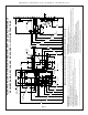
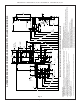
EZSTLDWS*1G EZSTL8WS*1G, 2G, 3G LZSTLDWS*1G LZSTL8WS*1G, 2G, 3G PLUMBING DIAGRAMS VERSATILE BI-LEVEL Bottle Filler Drain Bottle Filler Drain Bottle Filler Drain Bottle Filler Drain 1000002243 (Rev.
Tee 3/8” Water Inlet Evaporator R.H. Refrig. unit Page 15 Filter Assembly 1/4” Union regulator Bubbler L.H. Non-Refrig unit Solenoid Valve 3/8” Water Inlet Solenoid Valve regulator Bubbler Tee 3/8” Water Line from Bottle Filling Unit Standard EZ Bi-Level Pressurized Plumbing Diagram regulator Bubbler Solenoid Valve Evaporator R.H. Refrig.
EZSTLDWS*1G EZSTL8WS*1G, 2G, 3G LZSTLDWS*1G LZSTL8WS*1G, 2G, 3G Fig. 12 11 Basin Estanque Bassin Locknut Tuerca de Fijación Écrou de Blocage BUBBLER DETAIL DETALLE DEL GRIFO DETAIL DU BARBOTEUR Fig. 13 NOTE: When installing replacement bubbler and pedestal, tighten nut only to hold parts snug in position. Do Not Overtighten. NOTA: Al instalar el grifo y pedestal de reemplazo, apriete la tuerca unicamente para mantener las piezas en una posicion adjustada. No dede apretarse demasiado.
EZSTLDWS*1G EZSTL8WS*1G, 2G, 3G LZSTLDWS*1G LZSTL8WS*1G, 2G, 3G OPERATION OF QUICK CONNECT FITTINGS SIMPLY PUSHIN IN SIMPLY PUSH TUBE TO TUBE TOATTACH ATTACH A A TUBE TUBEIS IS SECURED SECURED INPOSITION POSITION IN B PUSH PUSHIN IN COLLET COLLET TORELEASE RELEASE TUBE TUBE TO C PUSHING BEFORE PUSHINGTUBE TUBE IN IN BEFORE PULLING TO PULLING IT IT OUT OUT HELPS HELPS TO RELEASE RELEASE TUBE TUBE Note: Screw the locknut hand tight to seal Fig. 15 Fig.
EZSTLDWS*1G ITEM NO. 28401C 55001109 0000001337 36216C 36322C 56092C 56229C 66703C 98900C 8B 97969C 9 10 11 12 13 14 55996C 1000004572 56073C 98734C 1000001600 98773C 98774C 15 98775C 16 17 98776C 98777C 18 19 20 21 22 23 24 25 26 27 28 98778C 98898C 0000000238 98724C 1000002062 1000001602 97446C 1000001994 1000001812 1000004447 35980C 36287C 1000004564 0000001339 1000000888 1000000944 1000000758 1000000759 29 30 NS NS NS = NOT SHOWN ITEM NO.