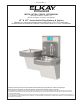
ENLZSTL8WS_1F Enhanced INSTALLATION, CARE & USE MANUAL Manual de instalación, cuidado y uso Manuel d’installation, d’entretien et d’utilisation LZ ™ & EZ ™ Series Bottle Filling Stations & Coolers Bebederos y estaciones llenadoras de botellas series LZ™ y EZ™ mejorados Remplisseuses de bouteille et fontaines à eau fraîche séries LZ™ et EZ™ améliorées *V ersatile cooler design allows units to be installed either left-hand high and right-hand low or left-low and right high.
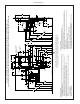
1000002120 (Rev. E - 09/17) E Page 2 B 7" 178mm 3 7/8" 98mm 2" 51mm 6 3/8" 162mm FINISHED FLOOR 7" 178mm 5 3/4" 146mm 6 3/8" 162mm C L 7" 178mm FIG.
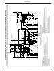
ALTERNATE ROUGH-IN FOR RIGHT-HAND HIGH, BOTTLE FILLER LOW MODELS – REQUIRES BASIN ASSY CHANGE Page 3 FILTER A ALTERNATE LOCATION 3 7/8" 98mm 6 3/8" 162mm 7" 178mm C L SOL FINI C L 24 1/2" 622mm 22 15/16" 583mm 19 7/16" 494mm F 34 5/16" 871mm 2" 51mm A PREFERRED LOCATION E O 9/32" (7mm) HOLES (12) FIG.
1000002120 (Rev.
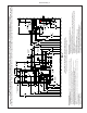
ALTERNATE ROUGH-IN FOR RIGHT-HAND LOW, BOTTLE FILLER HIGH MODELS – REQUIRES BASIN ASSY CHANGE Page 5 E D PREFERRED LOCATION 6 3/8" 162mm B C L 7" 178mm 3 7/8" 98mm 2" 51mm 6 3/8" 162mm FIG.
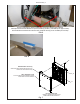
ENLZSTL8WS_1F HANGER BRACKETS INSTALLATION 1) Remove hanger bracket fastened to back of coolers by removing one (1) screw. 2) Determine your mounting configuration from the figures shown on pages 2 - 5. IMPORTANT NOTE: If the bottle filler is to be mounted on the left hand cooler, a basin assembly change will be needed. Refer to instructions on pages 13 - 15 prior to continuing. 3) Mount the hanger bracket as shown in Figures 1 (Pg. 2), 2 (Pg.3), 3 (Pg. 4), and 4 (Pg. 5).
ENLZSTL8WS_1F Instalación de los soportes de suspensión 1) Retire un (1) tornillo para retirar el soporte colgante fijado en la parte posterior del bebedero. 2) Determinar su configuración de montaje de las figuras que se muestran en las páginas 2 - 5. NOTA IMPORTANTE: Si el relleno de la botella se va a montar en el refrigerador de la mano izquierda, será necesario un cambio de montaje cuenca. Consulte las instrucciones en las páginas 13 - 15 antes de continuar.
ENLZSTL8WS_1F Installation de supports de suspension 1) Déposer la ferrure de suspension qui est fixée au dos de la fontaine à eau au moyen d’une (1) vis. 2) Déterminez votre configuration de montage à partir des chiffres indiqués sur les pages 2 - 5. NOTE IMPORTANTE: Si la charge de la bouteille doit être monté sur le refroidisseur de la main gauche, un changement de l’ensemble du bassin sera nécessaire. Consulter les instructions sur les pages 13 à 15 avant de poursuivre.
ENLZSTL8WS_1F Secure cooler frame to wall by installing (2) screws and washers (not supplied). Para fijar la estructura del bebedero a la pared, instale (2) tornillos y arandelas (no se proporcionan). Fixer le bâti de la fontaine à eau fraîche au mur à l’aide de deux (2) vis et rondelles (non fournies). FIG. 5 FIG.
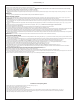
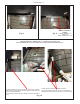
ENLZSTL8WS_1F Fig. 8 Fig. 9 BRACKET, WASHERS, & SCREWS SOPORTE, ARANDELAS Y TORNILLOS BRIDE, RONDELLES ET VIS BOTTLE FILLER PLUMBING CONNECTIONS CONEXIONES DE PLOMERÍA DE LA LLENADORA DE BOTELLAS RACCORDEMENTS DE TUYAUTERIE DE LA REMPLISSEUSE DE BOUTEILLE Fish 3/8 inch water line up through basin hole and hole in gasket. Pase la tubería de agua de 3/8" a través del orificio de la tarja y del orificio en la empaquetadura. Tirer la conduite d’eau de 3/8 po à travers le trou de la fontaine et le joint.
ENLZSTL8WS_1F BOTTLE FILLER ELECTRICAL CONNECTIONS CONEXIONES ELÉCTRICAS DE LA LLENADORA DE BOTELLAS RACCORDEMENTS ÉLECTRIQUES DE LA REMPLISSEUSE DE BOUTEILLE Connect wiring harness to the top of Cooler. Ensure all pins line up. Conecte el haz de cables en la parte superior del bebedero. Asegúrese de que todas las clavijas estén alineadas. Raccorder le faisceau de câbles au sommet de la fontaine à eau fraîche. Vérifier le bon alignement de toutes broches. Fig.
ENLZSTL8WS_1F 115V Refrigerated Wiring Diagram with Alpha/Numeric Display Diagrama de cableado de modelo refrigerado de 115 V con pantalla alfanumérica ORANGE 3 1 2 28 BLK RED FAN SOLENOID VALVE J2 10 1 8 J9 FUSE WHT RIBBED NON-REFRIGERATED MODEL J8 30 2 4 26 NFC BOARD (FILTER) JUMPER 6 TRANSFORMER RELAY J6 CONTROL BOARD GRN GND GND 5 2 COLD CONTROL 6 3 J7 WHT M 27 SILVER WHT 24 VAC C S EVAP. THERMISTER 29 OVERLOAD COND.
ENLZSTL8WS_1F INSTRUCTIONS TO MOVE THE BOTTLE FILLER & BASIN TO THE LEFT SIDE (NON-REFRIGERATED) FOR ALTERNATE MOUNTING VERSATILE BI-LEVEL INSTRUCCIONES PARA MOVER LA LLENADORA DE BOTELLAS Y LA TARJA HACIA EL LADO IZQUIERDO (NO REFRIGERADO) PARA REALIZAR UN MONTAJE ALTERNATIVO Y VERSÁTIL DE DOS NIVELES DÉPLACEMENT DE LA REMPLISSEUSE DE BOUTEILLE ET DE LA FONTAINE VERS LE CÔTÉ GAUCHE (NON RÉFRIGÉRÉ) DANS UNE AUTRE CONFIGURATION BI-NIVEAU Fig.
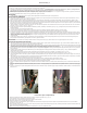
ENLZSTL8WS_1F INSTRUCTIONS CONTINUED... CONTINUACIÓN DE LAS INSTRUCCIONES... INSTRUCTIONS - SUITE... Refrigerated Cooler side: Before removing the shroud/basin assembly press the tabs on the panel mount connector and push it down through the basin. Lado del bebedero refrigerado: Antes de retirar el conjunto de recubrimiento y tarja, presione las lengüetas en el conector de montaje del panel y empújelas hacia abajo a través de la tarja.
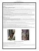
ENLZSTL8WS_1F INSTRUCTIONS CONTINUED... CONTINUACIÓN DE LAS INSTRUCCIONES... INSTRUCTIONS - SUITE... Refrigerated Cooler side: Before replacing the shroud/basin assembly, route the panel mount harness wires behind the top of the evaporator and out the left side of the refrigerated cooler. Verify that the wires are NOT loose and in the fan blade. Carefully tip the shroud basins assembly toward the cooler frame.
ENLZSTL8WS_1F Versatile Wrapper and Trim Kit Installation Instructions Instrucciones de instalación del kit de acabado y del revestimiento Instructions de pose de la trousse d’enveloppe et garniture polyvalente Left Hand Wrapper (High Side) 1) Remove existing wrapper by removing the (4) screws from bottom. 2) Screw trim piece to wrapper with (2) screws (provided) 3) Re-install wrapper with (4) screws. 4) Dispose of unused cover plate.
ENLZSTL8WS_1F INSTRUCTIONS CONTINUED... CONTINUACIÓN DE LAS INSTRUCCIONES... INSTRUCTIONS - SUITE... Left Hand Wrapper (Low Side) 1) Remove existing wrapper by removing the (4) screws from bottom. 2) Clip cover plate, sliding until plate sits flush with the wall. 3) Re-install wrapper with (4) screws. 4) Dispose of unused trim piece. Revestimiento del lado izquierdo (Lado bajo) 1) Retire los (4) tornillos de la parte inferior para retirar el revestimiento existente.
ENLZSTL8WS_1F PLUMBING DIAGRAMS / DIAGRAMAS DE PLOMERÍA / SCHÉMAS DE TUYAUTERIE VERSATILE BI-LEVEL / VERSÁTIL DE DOS NIVELES / POLYVALENT BI-NIVEAU Barb capped when not used Cerrado cuando no la use Raccord obturé s’il n’est pas utilisé Bottle Filler Drain Desagüe de la llenadora de botellas Écoulement remplisseuse de bouteille Bottle Filler Drain Desagüe de la llenadora de botellas Écoulement remplisseuse de bouteille Barb capped when not used Cerrado cuando no la use Raccord obturé s’il n’est pas utili
ENLZSTL8WS_1F 11 Basin Tarja Cuve Locknut Contratuerca Écrou de blocage BUBBLER DETAIL DETALLE DE LA BOQUILLA DÉTAIL DU BARBOTEUR Fig. 18 NOTE: When installing replacement bubbler and pedestal, tighten nut only to hold parts snug in position. Do Not Overtighten. Fig.
ENLZSTL8WS_1F Service Instructions Lower and Upper Shroud To access the refrigeration system and plumbing connections, remove four screws from bottom of cooler to remove the lower shroud. To remove the upper shroud for access to the pushbars, regulator, solenoid valve or other components located in the top of the unit, remove lower shroud, disconnect drain, remove four screws from tabs along lower edge of upper shroud, unplug two wires and water tube.
Page 21 Momentary Clear Error Codes Momentary Energy Save Mode Momentary Momentary Backlight Setting View Error Codes Momentary Momentary Water Temperature Flow Rate? Refrigeration Unit? Filter Unit? Momentary Minute (0-60 in 5min increments) AM/PM Are you sure? Momentary Yes - Clear error modes Momentary Set Energy Save Schedule On Flashes Error Codes Momentary Default operation 1 (= 25%) 2 (=50%) 3 (=75%) 4 (=100%) Momentary Set to “Cold” Temperature Momentary Set to Default Temper
1000002120 (Rev.
Momentanée Filter Unit? (Filtre?) Page 23 Momentanée Momentanée Clear Error Codes (Effacer les codes d’erreur) Momentanée Energy Save Mode (Mode d’économie d’énergie) View Error Codes (Afficher les codes d’erreur) Momentanée Backlight Setting (Rétroéclairage) Water Temperature (Température de l’eau) Flow Rate? (Débit?) Momentanée Momentanée Set Day/Time (Régler jour/heure) Refrigeration Unit? (Réfrigération?) Action Menu principal Momentanée Coldest (Très froid) Are you sure? (Confirmer
ENLZSTL8WS_1F Enhanced EZH2O Error Codes Error Code Error Description Corrective Action E001 Evaporator Thermistor Open Circuit E002 Evaporator Thermistor Short Circuit E003 Evaporator Low Temperature E004 Condenser Thermistor Open Circuit E005 Condenser Thermistor Short Circuit E006 Condenser Over Temperature • Verify cable connector is plugged into control board (10 pin connector on harness # 0000001225) • If error repeats, contact certified service professional • Check for excessive
ENLZSTL8WS_1F Códigos de Error EZH2O mejorada Código de error E001 E002 E003 E004 E005 E006 E007 Descripción del error Circuito abierto del termistor de evaporador Evaporador de termistor corto circuitot Evaporador baja temperatura Circuito abierto de termistor condensador Condensador de termistor corto circuito Condensador superior a la temperatura Action corrective • Verificar el conector del cable está enchufado en el tablero de control (10 conector perno arnés 0000001225 #) • Si se repite
ENLZSTL8WS_1F Codes d’erreur EZH2O renforcée Code d’erreur Description de l’erreur E001 Évaporateur thermistance Circuit ouvertt E002 Évaporateur thermistance Court Circuit E003 Faible température de l’évaporateur E004 Circuit ouvert thermistance de condenseur E005 Condensateur Thermistance Court Circuit E006 Condensateur au-dessus de la température Action corrective • Vérifiez le connecteur du câble est bien branché de contrôle des stupéfiants (10 broches sur harnais # 0000001225) • Si l’
ENLZSTL8WS_1F Pictured is unit only without bottle filler. En la ilustración solo se muestra la unidad sin la llenadora de botellas. Appareil illustré seul sans remplisseuse de bouteille. Note: Danger! Electrical shock hazard. Disconnect power before servicing unit. Nota: peligro! Peligro de descarga eléctrica. Desconecte antes de reparar la unidad Remarque : Danger ! Risque de choc électrique. Débrancher avant de réparer l’appareil..
ENLZSTL8WS_1F 115V PARTS LIST / LISTA DE PIEZAS DE 115 V / LISTE DES PIÈCES 115 V ITEM NO.
ENLZSTL8WS_1F This device complies with part 15 of the FCC Rules. Operation is subject to the following two (2) conditions: (1) This device may not cause harmful interference, and (2) this device must accept any interference received, including interference that may cause undesired operation. Changes or modifications not approved by the manufacturer could void the user’s authority to operate the equipment. This device complies with Industry Canada licence-exempt RSS standard(s).
ENLZSTL8WS_1F This page intentionally left blank 1000002120 (Rev.