
Use and Care Manual

Page 6
ENLZSTL8WS_1F
1000002120 (Rev. E - 09/17)
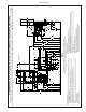
HANGER BRACKETS INSTALLATION
1) Remove hanger bracket fastened to back of coolers by removing one (1) screw.
2) Determine your mounting conguration from the gures shown on pages 2 - 5. IMPORTANT NOTE: If the bottle ller is to be mounted on the left hand cooler, a basin assembly
change will be needed. Refer to instructions on pages 13 - 15 prior to continuing.
3) Mount the hanger bracket as shown in Figures 1 (Pg. 2), 2 (Pg.3), 3 (Pg. 4), and 4 (Pg. 5).
NOTE: Hanger Bracket MUST be supported securely. Add xture support carrier if wall will not provide adequate support. Anchor hanger securely to wall using all six (6) 1/4 in. dia. mount-
ing holes.
IMPORTANT:
5-7/8 in. (150 mm) dimension from wall to centerline of trap must be maintained for proper t.
INSTALLATION OF COOLER
4) Hang only the refrigerated cooler on the hanger bracket. Be certain hanger bracket is properly in the slots on the cooler backs as shown in Figures 1 (Pg. 2), 2 (Pg.3), 3 (Pg. 4), and
(Fig. 4, Pg. 5).
5) Remove the four (4) screws holding the lower front panel at the bottom of each cooler. Remove the front panel by pulling straight down and set aside.
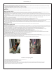
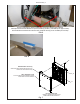
6) Unband the loose wires in the refrigerated cooler for the NFC board. (See Figure A below). Stretch it out and thread through the left side of the refrigerated cooler and into the right side of
the non-refrigerated cooler. Plug into the board that is behind the lter head. Since this cooler is not yet hanging on the wall, you can tip it forward to view the plug from the back to make it
easier to connect.
7) Hang the non-refrigerated cooler on the hanger bracket. Be certain hanger bracket is engaged properly in the slots on the cooler backs as shown in Figures 1, (Pg. 2), 2 (Pg. 3), 3 (Pg. 4), and 4
(Pg. 5).
8) Secure each cooler frame to wall by installing (2) screws and washers (not supplied). (See Fig. 5, Pg. 9). Make sure the screws engage in a structural member.
9) Connect the supply water to the lter inlet tube.
10) Connect the waterline from the outlet of the lter to the inlet of the evaporator in the refrigerated cooler by inserting it into the quick connector.
11) Connect the waterline from the solenoid in the non-refrigerated cooler to the open 1/4” inch tee tting in the refrigerated cooler.
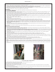
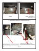
12) Locate the black and white wires coiled inside the non-refrigerated cooler. (See Fig. B below) Uncoil and remove the caps covering the loose ends of each. Find the black and white wires with the
extensions inside of the refrigerated cooler and remove the protective caps. Connect the wires from one cooler to the wires inside the other. NOTE: White to white, Black to black.
13) Find your cooler conguration on page 18 and connect the drain assembly together. The bottle ller drain in the top of the basin must be connected at this time also.
14) Install trap. Remove the slip nut and gasket from the trap and install them on the cooler waste line making sure that the end of the waste line ts into the trap. Assemble the slip nut and gasket to
the trap and tighten securely.
IMPORTANT: If it is necessary to cut the drain, loosen the screw at the black rubber boot and remove tube, check for leaks after re-assembly.
BOTTLE FILLER INSTALLATION
15) Remove two (2) mounting screws with 5/32" Allen wrench holding bottle ller to wall mounting plate (See Fig.7, Pg. 9). Note do not discard mounting screws, they will be needed to secure
bottle ller to wall mounting plate.
16) Remove wall mounting plate from Bottle Filler (see Fig 7, Pg. 9). Place wall mounting plate against wall on top of basin. Center the wall mounting plate side to side with the basin. Mark the six (6) mount-
ing holes with a pencil (See Fig. 1, Pg. 2). Place tape over wiring harness conection on top of cooler to prevent debris from falling into Connection (See Fig. 6, Pg. 9).
17) Remove wall mounting plate from wall. NOTE: Mounting plate MUST be supported securely. Add xture support carrier if wall will not provide adequate support.
18) Install wall mounting plate to wall using six (6) 7/16" obround mounting holes (mounting bolts not included) (See Fig. 7, Pg. 9). Use appropriate fasteners for your wall type.
19) Install gasket on bottom of bottle ller tower with gasket support bracket, (2) washers, & (2) screws (See Fig. 8, 9, Pg. 10).
20) Connect water line from cooler to 3/8" john guest tting. Connect wiring harness to the top of cooler. (See Fig. 11, Pg. 11).
21) Place Bottle Filler on the four (4) hooks on the mounting plate installed on wall. Make sure round boss in gasket ts in hole of basin. (See Fig. 12, Pg. 11).
22) Remove lter from carton, remove protective cap, attach lter to lter head by rmly inserting into head and rotating lter clockwise. Ensure that blue label can be read when lter is
installed. (reference Fig. 16, Pg 19.)
23) Turn water supply on and inspect for leaks. In both cooler and bottle ller. Fix all leaks before continuing.
24) Once cooler and bottle lter have been inspected for leaks and any leaks found corrected, plug cooler into wall.
25) Reinstall two mounting screws from rst step above. Caution, do not over tighten screws.
26) Once power is applied to the cooler the GREEN LED light will illuminate on the bottle ller showing good lter status along with the LCD Bottle Counter.
27) Verify proper dispensing by placing cup, hand, or any opaque object in front of sensor area and verify that the water dispenses. Note: the rst initial dispenses might have air in line which
may cause a sputter. This will be eliminated once all air is purged from the line.
28) Once unit tests out, install Lower Panels back on water coolers. (See page 16 for versatile wrapper installation). Units are now ready for use.
Instructions For Replacing Filters
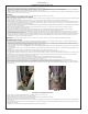
1) Remove lower cover on non-refrigerated unit by removing (4) screws (See Fig.A, Pg. 13).
2) Turn off water supply; dispense water to relieve pressure.
3) Turn used lter counterclockwise 1/4 turn to remove from lter head.
4) Remove cap from new lter and use to seal used lter.
5) Insert new lter into existing lter head and turn fully clockwise. Make sure you can read the label on the front of the lter once it is installed. (See Fig. 16 on Pg. 19).
6) Turn on water supply and run a minimum of two gallons of water through the lter to purge air any ne carbon particles from lter. Also run water through bottle ller.
Note: Filter status light will automatically reset once new lter is installed.
FIG. A FIG. B