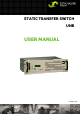
STATIC TRANSFER SWITCH UNB USER MANUAL UM_UNB_E_R04
Static Transfer Switch UNB User Manual Page 2 (28) Notes on this manual ATTENTION! Read this manual very carefully before installing and commissioning the specified module. This manual is a part of the delivered module. Familiarity with the contents of this manual is required for installing and operating the specified module. The rules for prevention of accidents for the specific country and the general safety rules in accordance with IEC 364 must be observed.
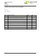
Static Transfer Switch UNB User Manual Page 3 (28) Current revision status of this user manual Revision: 04 Date: 2010-05-14 Revision Description of change Writer Date 01 First edition RTH 2007-04-26 02 Layout change, minor text modifications, UNB30.0 inserted. RTH 2008-01-14 03 Minor text modifications, “Remote switch ON” added. RTH 2008-06-05 04 Minor text modifications at section 2.2 "Operating modes".
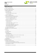
Static Transfer Switch UNB User Manual Page 4 (28) Table of Contents 1A. SAFETY INSTRUCTIONS..............................................................................................................................................5 1B. ELECTRIC WASTE DISPOSAL ......................................................................................................................................5 2. GENERAL INFORMATION........................................................................................
Static Transfer Switch UNB User Manual Page 5 (28) 1A. Safety Instructions Warning! Because several components of operating electrical modules are charged by dangerous voltage, the improper handling of electrical modules may be the cause of accidents involving electrocution, injury, or material damages. Operation and maintenance of electrical modules must be performed by qualified skilled personnel such as electricians in accordance with EN 50110-1 or IEC 60950.
Static Transfer Switch UNB User Manual Page 6 (28) 2. General Information An electronic transfer switch is to be used if critical consumer loads have to be switched over nearly interruption free between two AC sources (usually inverters and substitute-mains) with a reaction time which is not able to be reached with a manual (mechanical) bypass switch.
Static Transfer Switch UNB User Manual Page 7 (28) 2.2 Operating modes The static transfer switch UNB is designed for the operating modes “inverter priority” and “mains priority” alternatively. Source 1 is defined as priority source, source 2 is defined as substitute source. Source 1 feeds the load as long as source 1 works faultlessly. 2.2.1 "Inverter priority" (default setting) REMARK: The unit's default setting is "Inverter priority". In this case the inverters are source 1, mains is source 2.
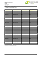
Static Transfer Switch UNB User Manual Page 8 (28) 3. Type List and Main Data Type Designation Material Code Battery Voltage (VDC) UNB5.0-24 600-050-411.00 24 Rated Output Power (kVA @ 230VAC) 5.0 UNB5.0-48 600-050-511.00 48 5.0 UNB5.0-60 600-050-611.00 60 5.0 UNB5.0-110 600-050-711.00 108 5.0 UNB5.0-220 600-050-811.00 216 5.0 UNB12.5-24 600-125-411.00 24 12.5 UNB12.5-48 600-125-511.00 48 12.5 UNB12.5-60 600-125-611.00 60 12.5 UNB12.5-110 600-125-711.00 108 12.
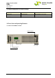
Static Transfer Switch UNB User Manual Page 9 (28) 3.1 Optional equipment for UNB assembly: Article Article code Suitable for: Mounting-kit 880-MEC-MKT.01 UNB5.0 & UNB12.5 type series Mounting-kit 880-MEC-MKT.03 UNB23.0, UNB30.0 & UNB40.0 type series 3.2 Front View and Operating Elements 3.2.1 Front view UNB5.0/12.
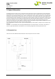
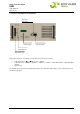
Static Transfer Switch UNB User Manual Page 10 (28) 3.2.2 Front view UNB23.0/30.0/40.0kVA Sub-Min-D (not used) Digital Display CAN Connectors LED Indications Adjustment Keys All operating elements and indicators are located at the front of the modules: 4 adjustment keys: (up), (down), “ESC”, “ENTER”. 7 LED indications: “STANDBY”, “SOURCE 1”, “SOURCE 2”, “SYNCHR.”, “LOAD ON INVERTER”, “LOAD ON MAINS”, “ALARM”.
Static Transfer Switch UNB User Manual Page 11 (28) 3.3 Electrical Connectors 3.3.1 Input terminals The UNB is equipped with two AC inputs, one for the inverter and the other for the substitute-mains. Both sources must have the same frequency and the same nominal voltage level. Because there are no protection fuses integrated in the unit, both sources must be protected externally. If several inverters are connected in parallel, the parallel connection of the inverter outputs has to be arranged externally.
Static Transfer Switch UNB User Manual Page 12 (28) 3.3.3 Connectors UNB 5.0 and UNB 12.5kVA 1 3 X1 2 4 View from the rear: UNB 5.0/12.
Static Transfer Switch UNB User Manual Page 13 (28) 3.3.4 Connectors UNB 23.0kVA 1 1 X2 3 3 2 X1 2 4 View from the rear: UNB 23.
Static Transfer Switch UNB User Manual Page 14 (28) 3.3.5 Connectors UNB 30.0kVA & UNB 40.0kVA 1 1 3 3 3 2 View from the rear: UNB 30.0/40.
Static Transfer Switch UNB User Manual Page 15 (28) 3.3.6 Pinning of the CAN bus connectors The UNB is equipped with 2 CAN connectors (CAN1 and CAN2) at the front of the unit. CA N 1 6 CAN bus connector (socket outlet RJ11, 6 pole) Pinning table: Pin Signals CAN1 Signals CAN2 Designation 1 CAN_V+ DC-Supply +8...15V 2 CAN_V+ DC-Supply +8...15V 3 CAN_H Signal (high) 4 CAN_L Signal (low) 5 CAN_V- DC-Supply Ground 6 CAN_V- DC-Supply Ground 3.3.
Static Transfer Switch UNB User Manual Page 16 (28) 3.5 Cooling/Air flow direction The unit is cooled with an internal fan. The airflow is from the front to rear side. The fan is monitored and speed controlled by device temperature. For a sufficient airflow a minimum space (A) of 50 mm between the unit and the rear cabinet wall as well as an unobstructed influx of supply air from front side is necessary.
Static Transfer Switch UNB User Manual Page 17 (28) 3.6 CAN-Bus Communication Interface The UNB is equipped with a serial data interface according to CAN (= Controller Area Network) -specification. Two CAN-Bus connectors are integrated in the front plate of the unit. The UNB communicates via CAN-Bus with the connected inverters and a possibly implemented supervision monitoring device (UPC3 or MU1000C).
Static Transfer Switch UNB User Manual Page 18 (28) 4. Handling 4.1 Storage The UNB must be stored in a dry, dust free environment with a storage temperature according to specified data (see section 7). 4.2 Commissioning Note: Before commissioning the module make sure that the voltage level of both input sources and the battery voltage correspond to the values according to the type plate of the UNB. To mount the inverter in a 19’’ compatible cabinet, a mounting-kit according to section 3.1 is necessary.
Static Transfer Switch UNB User Manual Page 19 (28) 4.3.
Static Transfer Switch UNB User Manual Page 20 (28) 4.3.3 LCD panel / Indication of measuring values & alarm messages In the initial state the display shows the measuring values of the input sources (AC output voltage of inverter, mains voltage, output current, date and time, additional frequencies of inverter and mains and battery voltage as well as the total DC-current). (The example above shows six registered inverters) Display [1] shows the initial state (basic display).
Static Transfer Switch UNB User Manual Page 21 (28) 4.4 Parameter adjustments REMARK: The configuration of the system during commissioning takes place with the service menu 1 and 2 and the calibration menu. They are code protected to guard against illegal parameter changes. The special documents only are available for qualified and skilled service personnel. In the following the adjustable parameters in the customer menu (available for each customer) are described. 4.4.
Static Transfer Switch UNB User Manual Page 22 (28) 4.4.2 Diagram “Customer menu” The customer menu can be entered from the basic display by pressing ENTER for around 3 seconds and then press ENTER again. A list of all selectable individual collective failures (CF) is shown on the previous page.
Static Transfer Switch UNB User Manual Page 23 (28) The final display provides information about the currently used firmware version.
Static Transfer Switch UNB User Manual Page 24 (28) 5. Maintenance In general, the static transfer switch UNB is maintenance-free. A yearly inspection with following checks is simply recommended: Correct fan operation Mechanical inspection Removal of dust and dirt, especially on radiating surfaces Check for internal dust or humidity Attention! Dust combined with dew or water may influence or destroy the internal electronic circuits. Dust inside the unit can be blown out with dry compressed air.
Static Transfer Switch UNB User Manual Page 25 (28) 7. Technical Specifications Type designation Please see section 1 “Type List/Main Data” Material code Please see section 1 “Type List/Main Data” AC input: Nominal input voltage source 1 + 2 220/230/240VAC, adjustable Input voltage tolerance ±20% Input frequency range 48- 52Hz/ 58-62Hz, adjustable Synchronization range ±2Hz (in combination with inverters of series PWS the range must be adjusted to ±0.5Hz).
Static Transfer Switch UNB User Manual Page 26 (28) Environmental: Ambient temperature operation: -20°C to +55°C; storage: -40°C to + 85°C Climatic conditions acc. to IEC 721-3-3 class 3K3/3Z1/3B1/3C2/3S2/3M2 Dust <1mg/m3 Max. installation altitude ≤1500m Audible noise ≤45dBA at 1m distance Mechanical: Type of construction 19’’- compatible rack acc.
Static Transfer Switch UNB User Manual Page 27 (28) 7.1 Dimensional Drawings UNB5.0/12.5 kVA: 7.2 Dimensional Drawings UNB23.0kVA, UNB30.0kVA & 40.
Static Transfer Switch UNB User Manual Page 28 (28) 7.3 Photo UNB5.0/12.5kVA Please see first cover page 7.4 Photo UNB23.0/30.0/40.