
User manual

Static Transfer Switch
UNB
User Manual
Page 10 (28)
ELTEK VALERE DEUTSCHLAND ©2009 UM_UNB_E_R04
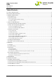
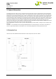
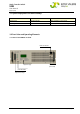
3.2.2 Front view UNB23.0/30.0/40.0kVA
Sub-Min-D
(not used)
Digital Display CAN Connectors
LED Indications
Adjustment Keys
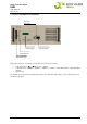
All operating elements and indicators are located at the front of the modules:
4 adjustment keys: (up), (down), “ESC”, “ENTER”.
7 LED indications: “STANDBY”, “SOURCE 1”, “SOURCE 2”, “SYNCHR.”, “LOAD ON INVERTER”, “LOAD ON MAINS”,
“ALARM”.
Digital display
For detailed information concerning operating elements, LED indicators, digital display and connectors please see
the following chapters.