
User manual

Static Transfer Switch
UNB
User Manual
Page 4 (28)
ELTEK VALERE DEUTSCHLAND ©2009 UM_UNB_E_R04
Table of Contents
1A. SAFETY INSTRUCTIONS..............................................................................................................................................5
1B. ELECTRIC WASTE DISPOSAL......................................................................................................................................5
2. GENERAL INFORMATION................................................................................................................................................6
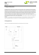
2.1 Example of use .........................................................................................................................................................6
2.2 Operating modes......................................................................................................................................................7
2.2.1 "Inverter priority" (default setting)....................................................................................................................................7
2.2.2 "Mains priority" .......................................................................................................................................................................7
3. TYPE LIST AND MAIN DATA..........................................................................................................................................8
3.1 Optional equipment for UNB assembly: .............................................................................................................9
3.2 Front View and Operating Elements ...................................................................................................................9
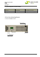
3.2.1 Front view UNB5.0/12.5kVA...............................................................................................................................................9
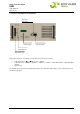
3.2.2 Front view UNB23.0/30.0/40.0kVA............................................................................................................................... 10
3.3 Electrical Connectors........................................................................................................................................... 11
3.3.1 Input terminals .................................................................................................................................................................... 11
3.3.2 Output terminals................................................................................................................................................................. 11
3.3.3 Connectors UNB 5.0 and UNB 12.5kVA ........................................................................................................................ 12
3.3.4 Connectors UNB 23.0kVA ................................................................................................................................................ 13
3.3.5 Connectors UNB 30.0kVA & UNB 40.0kVA................................................................................................................... 14
3.3.6 Pinning of the CAN bus connectors ............................................................................................................................... 15
3.3.7 Connector (Sub-Min-D, 9-pole)......................................................................................................................................... 15
3.5 Cooling/Air flow direction ................................................................................................................................... 16
3.6 CAN-Bus Communication Interface .................................................................................................................. 17
4. HANDLING...................................................................................................................................................................... 18
4.1 Storage .................................................................................................................................................................... 18
4.2 Commissioning....................................................................................................................................................... 18
4.3 Operation................................................................................................................................................................. 18
4.3.1 LED indication ...................................................................................................................................................................... 18
4.3.2 Adjustment keys................................................................................................................................................................. 19
4.3.3 LCD panel / Indication of measuring values & alarm messages ............................................................................. 20
4.4 Parameter adjustments ...................................................................................................................................... 21
4.4.1 Table “Adjustable Parameters” (customer menu) ...................................................................................................... 21
4.4.2 Diagram “Customer menu” ............................................................................................................................................... 22
5. MAINTENANCE ............................................................................................................................................................. 24
6. TROUBLE SHOOTING...................................................................................................................................................24
7. TECHNICAL SPECIFICATIONS..................................................................................................................................... 25
7.1 Dimensional Drawings UNB5.0/12.5 kVA: ...................................................................................................... 27
7.2 Dimensional Drawings UNB23.0kVA, UNB30.0kVA & 40.0 kVA: ...............................................................27
7.3 Photo UNB5.0/12.5kVA ......................................................................................................................................28
7.4 Photo UNB23.0/30.0/40.0kVA .........................................................................................................................28