FULL MOSFET AMPLIFIER SERIES INSTALLATION & OPERATING MANUAL EINBAU- & BEDIENUNGSANLEITUNG
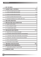
CONTENTS 1. KEY FEATURES 2. CONNECTIONS & CONTROLS 6-15 2.1 FRONT & REAR PANEL EA1450XT 6-7 2.2 FRONT & REAR PANEL EA2250XT 8-9 2.3 FRONT & REAR PANEL EA4150XT 10-11 2.4 FRONT & REAR PANEL EA460-300XT 12-14 2.5 SPEAKER IMPEDANCE & POWER WIRE INFO 15 3. AMPLIFIER MOUNTING 15 4. WIRE ROUTING AND CONNECTIONS 16 4.1 MAIN POWER WIRES 16 4.2 RCA & REMOTE WIRES 16 4.3 LOUDSPEAKER WIRES 16 5. CROSSOVER ADJUSTMENTS 17-19 5.1 SELECTING THE OPERATION MODE 17 5.
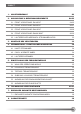
INHALT 1. HAUPTMERKMALE 2. ANSCHLÜSSE & BEDIENUNGSELEMENTE 23 24-33 2.1. FRONT & REAR PANEL EA1450XT 24-25 2.2 FRONT & REAR PANEL EA2250XT 26-27 2.3 FRONT & REAR PANEL EA4150XT 28-29 2.4 FRONT & REAR PANEL EA460-300XT 30-32 2.5 LAUTSPRECHER-IMPEDANZ & STROMKABEL INFOS 33 3. MONTAGE DES VERSTÄRKERS 33 4. VERKABELUNG / ELEKTRISCHER ANSCHLUSS 34 4.1 HAUPT-STROMKABEL 34 4.2 CINCH- & REMOTE KABEL 34 4.3 LAUTSPRECHERKABEL 34 5. EINSTELLUNG DER FREQUENZWEICHE 35 5.
Congratulations! And thank you for choosing this EMPHASER car audio amplifier! To maximize the performance of this amplifier and your car audio system install, we recommend that you acquaint yourself thoroughly with all capabilities and features of the EMPHASER amplifier model you have purchased. Please read this manual carefully, before attempting the installation. Please retain this manual and your purchasing/installation receipts for future reference.
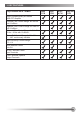
1. KEY FEATURES Key Features EA-XT AMPS 1450 1 CH 2250 2 CH 4150 4 CH 460-300 5 CH Quasi-Complementary N-Channel MOS-FET Amplifier Lowpass Filter Control Range: 40–200 Hz with 12 dB/oct . Highpass Filter Control Range: 40–200 Hz with 12 dB/oct . Subsonic Filter Control Range for Sub-CH: 10 Hz – 50 Hz with 12 dB/oct . Phase Shift Control Range for Sub-CH: 0° – 180° continuously variable Input Sensitivity Control Range: 0.
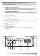
2. CONNECTIONS & CONTROLS 2.1 FRONT PANEL EA1450XT 1 RCA INPUTS L/R-CH Low-level stereo RCA signal input for connection to the line-out of the head-unit (sub-out). 2 INPUT GAIN CONTROL Input gain control potentiometer, allowing to match the output voltage of the headunit’s RCA line-outs to the amplifier input section. 3 PHASE CONTROL Phase control potentiometer for the relative phase adjustment of the subwoofer(s) connected to the amplifier output terminals.
2. CONNECTIONS & CONTROLS 2.1 REAR PANEL EA1450XT 8 POWER LED / PROTECTION LED Green Power-LED, signaling correct operation of the amplifier. Red “protection” LED, signaling faulty speaker connections or general malfunction of the amplifier. 9 GND POWER INPUT TERMINAL Moulded direct power input terminal to connect the amplifier to the negative or ground wire of the vehicle. 10 REMOTE INPUT TERMINAL Terminal to connect the amplifier to the automatic (remote) turn-on/turn-off lead of the head-unit.
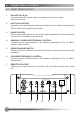
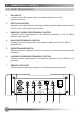
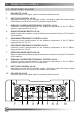
2. CONNECTIONS & CONTROLS 2.2 FRONT PANEL EA2250XT 1 RCA INPUTS Low-level stereo RCA signal input for connection with line-out of the head-unit (sub-out). 2 INPUT GAIN CONTROL Input gain control potentiometer, allowing to match the output voltage of the headunit’s RCA line-outs to the amplifier input section. 3 SUBSONIC CROSSOVER FREQUENCY CONTROL Crossover control potentiometer for the frequency adjustment of the 12 dB/oct. subsonic high-pass filter.
2. CONNECTIONS & CONTROLS 2.2 REAR PANEL EA2250XT 8 POWER LED / PROTECTION LED Green Power-LED, signaling correct operation of the amplifier. Red “protection” LED, signaling faulty speaker connections or general malfunction of the amplifier. 9 GND POWER INPUT TERMINAL Moulded direct power input terminal to connect the amplifier to the negative or ground wire of the vehicle.
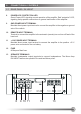
2. CONNECTIONS & CONTROLS 2.3 FRONT PANEL EA4150XT 1 RCA INPUTS 1/2-CH Low-level stereo RCA signal input for connection with head-unit. 2 INPUT GAIN CONTROL 1/2-CH Input gain control for 1/2-CH amplifier section - allowing to match the output voltage of the head-unit‘s RCA line-outs to the amplifier input section. 3 SUBSONIC CROSSOVER FREQUENCY CONTROL 1/2-CH Crossover control potentiometer for the frequency adjustment of the 12 dB/oct. subsonic high-pass filter of CH 1/2.
2. CONNECTIONS & CONTROLS 2.3 REAR PANEL EA4150XT 11 POWER LED / PROTECTION LED Red „protection“ LED, signalling faulty connections or malfunction of the amplifier. Green Power-LED, signalling correct operation of the amplifier. 12 GND POWER INPUT TERMINAL Moulded direct power input terminal to connect the amplifier to the negative or ground wire of the vehicle. 13 REM REMOTE INPUT TERMINAL Terminal to connect the amplifier to the (remote) turn-on /turn-off lead of the headunit.
2. CONNECTIONS & CONTROLS 2.4 FRONT PANEL EA460-300XT 1 RCA INPUTS 1/2-CH Low-level stereo RCA signal input for connection with head-unit. 2 RCA INPUTS 3/4-CH Low-level stereo RCA signal input for connection with head-unit. 3 INPUT GAIN CONTROL 1/2-CH Input gain control for 1/2-CH amplifier section - allowing to match the output voltage of the head-unit‘s RCA line-outs to the amplifier input section.
2. CONNECTIONS & CONTROLS 2.4 FRONT PANEL EA460-300XT 12 LOW PASS FREQUENCY CONTROL 5-CH Crossover control potentiometer for the frequency adjustment of the 12 dB/oct. low-pass filter for CH 5. 13 OPERATION MODE SWITCH 5-CH Switch to select the operation mode of the electronic filter driving 5-CH section of the amplifier. 14 SUBSONIC FREQUENCY CONTROL 5-CH Crossover control potentiometer for the frequency adjustment of the 12 dB/oct. subsonic high-pass filter for CH 5.
2. CONNECTIONS & CONTROLS 2.4 REAR PANEL EA460-300XT 16 POWER LED / PROTECTION LED Red „protection“ LED, signaling faulty speaker connections or general malfunction of the amplifier. Green Power-LED, signaling correct operation of the amplifier. 17 GND POWER INPUT TERMINAL Moulded direct power input terminal to connect the amplifier to the negative or ground pole of the car battery.
2.5 Speaker Impedance & POWER WIRE INFO The heat dissipation capacity of this amplifier line has been designed to cope with low impedance loads.
4. WIRE Routing AND CONNECTIONS 4.1 Main Power WIRES Run the positive main power cable („+12 V“) directly from the positive terminal of the car battery to the amplifier. For protection of your car audio system against electrical fire hazards, resulting from a short-circuit of the main power cable to chassis ground a main fuse holder must be inserted within the first 30 cm of the positive main power cable.
5. CROSSOVER ADJUSTMENTS 5.1 Selecting the Operation Mode You must select and set the appropriate operation mode before you can attempt any of the crossover frequency and gain adjustments. This setting depends on the speaker system connected to the amplifier. Select the appropriate operation mode as follows: ➡ Select HIGHPASS, if the speaker system is a component-, coaxial- or triaxial- type. ➡ Select BANDPASS in case of a kickbass system, or a subwoofer system.
5.4 SUBSONIC HIGHPASS CROSSOVER FREQUENCY ADJUSTMENT When driving a subwoofer in bandpass (“BPF”) operation mode, you should also adjust the subsonic highpass frequency. This is done by adjusting the “HPF” potentiometer. This setting depends the size and the power handling of the installed subwoofer system. The higher the subsonic crossover frequency is set, the higher the mechanical power handling of the connected subwoofer system will be.
5.6 PHASE-SHIFT ADJUSTMENT The phase shift function of the EA1450XT/EA460-300XT can not be deactivated, as it is permanently in the signal chain. The phase-shift control enables you to match the acoustical phase relations of subwoofer and the speaker system playing in the front doors. The target is, that both speaker systems, normally separated by approx. 3m of distance, shall play acoustically “in-phase” at the drivers seat location.
6. TECHNICAL SPECIFICATIONS / TECHNISCHE SPEZIFIKATIONEN EA1450 XT DE MONO VERSTÄRKER 460 W x 1 @ 4 Ohm (< 0.1 % THD / 14.4 V) 630 W x 1 @ 2 Ohm (< 0.1 % THD / 14.4 V) Frequenzgang: 20 Hz – 20 kHz Eingangsimpedanz: 24 kOhm Variable Eingangsempfindlichkeit: 0.25 – 6 V Dämpfungsfaktor @ 4 Ohm: > 200 Signal-Rauschabstand: > 85 dB Dimensionen BxHxT: 388 x 54 x 180 mm EN MONO AMPLIFIER 460 W x 1 @ 4 ohms (< 0.1 % THD/14.4 V) 630 W x 1 @ 2 ohms (< 0.1 % THD/14.
EA4150 XT DE 4-KANAL VERSTÄRKER 125 W x 4 @ 4 Ohm (< 0.1 % THD / 14.4 V) 200 W x 4 @ 2 Ohm (< 0.1 % THD / 14.4 V) 400 W x 2 @ 4 Ohm (< 0.1 % THD / 14.4 V) Frequenzgang: 20 Hz – 20 kHz Eingangsimpedanz: 24 kOhm Variable Eingangsempfindlichkeit: 0.25 – 6 V Dämpfungsfaktor @ 4 Ohm: > 200 Signal-Rauschabstand: > 85 dB Dimensionen BxHxT: 388 x 54 x 180 mm EN 4-CHANNEL AMPLIFIER 125 W x 4 @ 4 ohms (< 0.1 % THD / 14.4 V) 200 W x 4 @ 2 ohms (< 0.1 % THD / 14.4 V) 400 W x 2 @ 4 ohms (< 0.1 % THD / 14.
Herzlichen Glückwunsch! Wir danken Ihnen, dass Sie sich zum Kauf dieses EMPHASER Verstärkers entschieden haben. Damit Sie die Wiedergabequalität und die Leistungsfähigkeit Ihres Verstärkers voll ausschöpfen können, möchten wir Sie bitten, sich eingehend mit den Möglichkeiten und technischen Features dieses Verstärkers vertraut zu machen. Lesen Sie deshalb die nachfolgenden Abschnitte sorgfältig durch und bewahren Sie diese Bedienungsanleitung für später auf.
1. HAUPTMERKMALE Hauptmerkmale EA-XT Verstärker 1450 1 CH 2250 2 CH 4150 4 CH 460-300 5 CH Quasi-Komplementärer N-Channel MOS-FET Amp Tiefpassfilter Regelbereich: 40–200 Hz bei 12 dB/oct . Hochpassfilter Regelbereich: 40–200 Hz bei 12 dB/oct . Subsonic-Filter Regelbereich für Sub-CH: 10 Hz – 50 Hz bei 12 dB/oct . Phasenverschiebung Regelbereich für Sub -CH: 0° – 180° kont. veränderbar Eingangsempfindlichkeit Regelbereich: 0.
2. ANSCHLÜSSE & BEDIENUNGSELEMENTE 2.1 FRONT PANEL EA1450XT 1 CINCH INPUTS L/R Cinch Eingänge für den Anschluss an die Cinch Ausgänge des Steuergerätes. 2 REGLER EINGANGSEMPFINDLICHKEIT Poti zur Anpassung an die Ausgangsspannung des Steuergerätes. 3 PHASENREGLER 4 REGLER SUBSONIC TRENNFREQUENZ 5 X-OVER MODUS SCHALTER Schalter zum Einstellen der Arbeitsweise der integrierten elektronischen Frequenzweiche.
2. ANSCHLÜSSE & BEDIENUNGSELEMENTE 2.1 rear PANEL EA1450XT 8 POWER LED / PROTECTION LED Grüne „Power“ LED, signalisiert den normalen Betriebszustand der Endstufe im eingeschalteten Zustand. Rote „Protection“ LED, signalisiert eine generelle Fehlfunktion der Endstufe, wie z.B. Kurzschluss an den Lautsprecherausgängen, Überhitzung sowie Gleichspannung an den LS-Ausgängen. 9 GND POWER INPUT TERMINAL Druckgussterminal zum direkten Anklemmen der Masseverbindung.
2. ANSCHLÜSSE & BEDIENUNGSELEMENTE 2.2 FRONT PANEL EA2250XT 1 CINCH INPUTS L/R Cinch Eingänge für den Anschluss an die Cinch Ausgänge des Steuergerätes. 2 REGLER EINGANGSEMPFINDLICHKEIT Poti zur Anpassung an die Ausgangsspannung des Steuergerätes 3 REGLER SUBSONIC TRENNFREQUENZ Poti zum Einstellen der Subsonic Hochpass-Trennfrequenz an der integrierten elektronischen 12 dB/Okt. Frequenzweiche.
2. ANSCHLÜSSE & BEDIENUNGSELEMENTE 2.2 REAR PANEL EA2250XT 8 POWER LED / PROTECTION LED Grüne „Power“ LED, signalisiert den normalen Betriebszustand der Endstufe im eingeschalteten Zustand. Rote „Protection“ LED, signalisiert eine generelle Fehlfunktion der Endstufe, wie z.B. Kurzschluss an den Lautsprecherausgängen, Überhitzung sowie Gleichspannung an den LS-Ausgängen. 9 GND POWER INPUT TERMINAL Druckgussterminal zum direkten Anklemmen der Masseverbindung.
2. ANSCHLÜSSE & BEDIENUNGSELEMENTE 2.3 FRONT PANEL EA4150XT 1 CINCH INPUTS 1/2-CH Cinch Eingänge für den Anschluss an die Cinch Ausgänge CH 1/2 des Steuergerätes. 2 REGLER EINGANGSEMPFINDLICHKEIT 1/2 CH Poti zur Anpassung an die Ausgangsspannung von CH 1/2 des Steuergerätes. 3 REGLER SUBSONIC TRENNFREQUENZ 1/2 CH Poti zum Einstellen der Subsonic Hochpass-Trennfrequenz an der integrierten elektronischen 12 dB/Okt. Subsonic Frequenzweiche für CH 1/2.
1 2. 2 3 4 5 6 7 8 9 10 ANSCHLÜSSE & BEDIENUNGSELEMENTE 2.4 REAR PANEL EA4150XT 11 POWER LED / PROTECTION LED Grüne „Power“ LED, signalisiert den normalen Betriebszustand der Endstufe im eingeschalteten Zustand. Rote „Protection“ LED, signalisiert eine generelle Fehlfunktion. 12 GND POWER INPUT TERMINAL Druckgussterminal zum direkten Anklemmen der Masseverbindung. 13 REMOTE INPUT TERMINAL Druckgussterminal für die automatische Ein-bzw.
2. ANSCHLÜSSE & BEDIENUNGSELEMENTE 2.4 FRONT PANEL EA460-300XT 1 CINCH INPUTS CH 1/2 Cinch Eingänge für den Anschluss an die Cinch Ausgänge CH 1/2 des Steuergerätes. 2 CINCH INPUTS CH 3/4 Cinch Eingänge für den Anschluss an die Cinch Ausgänge CH 3/4 des Steuergerätes. 3 REGLER EINGANGSEMPFINDLICHKEIT CH 1/2 Poti für die Anpassung an die Ausgangsspannung von CH 1/2 des Steuergerätes.
2. ANSCHLÜSSE & BEDIENUNGSELEMENTE 2.4 FRONT PANEL EA460-300XT 12 REGLER SUBSONIC TRENNFREQUENZ CH 5 Poti zum Einstellen der Subsonic Hochpass-Trennfrequenz an der integrierten elektronischen 12 dB/Okt. Frequenzweiche. für CH 5. 13 X-OVER-MODUSSCHALTER CH 5 Schalter zum Einstellen der Arbeitsweise der integrierten elektronischen Frequenzweiche. Je nach Schalterstellung arbeitet der Verstärker im Fullrange (FULL), also Vollbereichs- oder Bandpass (BPF) Betrieb.
2. ANSCHLÜSSE & BEDIENUNGSELEMENTE 2.4 REAR PANEL EA460-300XT 16 POWER LED / PROTECTION LED Grüne „Power“ LED, signalisiert den normalen Betriebszustand der Endstufe im eingeschalteten Zustand. Rote „Protection“ LED, signalisiert eine generelle Fehlfunktion der Endstufe, wie z.B. Kurzschluss an den Lautsprecherausgängen, Überhitzung sowie Gleichspannung an den LS-Ausgängen. 17 GND POWER INPUT TERMINAL Druckgussterminal zum direkten Anklemmen der Masseverbindung.
2.5 LAUTSPRECHER ImpedanZ & STROMKABEL INFOs Die Wärmekapazität des Kühlkörpers dieser Endstufe wurde bei dieser Verstärker-Serie für niederohmige Lasten ausgelegt.
4. Verkabelung / Elektrischer Anschluss 4.1 HAUPT-STROMKABEL Verlegen Sie nun das Pluskabel direkt von der Batterie zum Verstärker. Innerhalb der ersten 30 cm nach dem Pluspolklemmenabgriff muss eine Hauptsicherung angebracht werden (Absicherung des Pluskabels gegen Kurzschluss auf Fahrzeug-Masse und dadurch resultierendem Kabelbrand!) Verwenden Sie eine dem Stromkabelquerschnitt entsprechende HauptSicherung. Schliessen Sie nun das Minuskabel am Verstärker an und an eine Massepunkt im Fahrzeug an.
5. EINSTELLUNG DER FREQUENZWEICHE 5.1 WAHL des Operationsmodus Stellen Sie den passenden Operationsmodus ein, bevor Sie die Einstellungen der Trennrequenz und Eingangsempfindlichkeit vornehmen. Diese Einstellungen sind vom verwendeten Lautsprechersystem abhängig. Wählen Sie den Modus wie folgt aus: ➡ HOCHPASS ➡ BANDPASS falls das verwendete Lautsprechersystem ein Komponenten-, Koaxial- , oder Triaxial-System ist. falls das verwendete Lautsprechersystem ein Kickbass oder Subwoofersystem ist.
5.4 SUBSONIC HOCHPASS TRENNFREQUENZ Um den angeschlossenen Subwoofer von unnötiger Hubarbeit im subsonischen Bereich zu schützen, verfügt diese Endstufe über einen immer im Signalweg liegenden Subsonic-Hochpass (d.h. er lässt sich nicht ausschalten!). Das Subsonicfilter lässt sich aber auf 10 Hz herunterregeln und hat bei einer so tief liegenden Einsatzfrequenz keinen hörbaren Einfluss auf die Basswiedergabe mehr. Das „Subsonicfilter“ schneidet alle Frequenzen unter dem eingestellten Wert mit 12 dB/Okt.
5.6 AnpassUNG DES PHASE-SHIFTS Die Phaseshift-Regler von EA1450XT und EA460-300XT befinden sich fest in der Signalkette und lassen sich nicht abschalten. Der Phase-Shift Regler ermöglicht die Beeinflussung der Phasenlage des angeschlossenen Subwoofer Systems. Mit diesem Regler – und gegebenenfalls durch zusätzliches Umpolen des Subwoofers, ist es möglich eine perfekte akustische Phasenlage zwischen dem Subwoofer und dem Frontsystem (oder auch den Kickbässen, wenn vorhanden) zu erzielen.
7. EMPHASER Limited WarrantY Dear customer Please read the warranty specifications below carefully. Should your EMPHASER product require warranty service, please return it to the retailer from whom it was purchased or the distributor in your country. Please do not send any product to EMPHASER Inc. U.S.A. Should you have difficulty in finding an authorized EMPHASER service center, details are available from your local distributor.
8. WARRANTY CARD / GARANTIEKARTE g 2 Jahre Gerätegewährleistun Months 24 : nty rra Wa Limited n approval only) (Valid with authorized Model name: installatio □ EA1450 XT □ EA2250 XT □ EA4150 XT □ EA460-300 XT Date of purchase/Kaufdatum: Ser. Nr.
Emphaser Inc., Wyoming, Michigan, U.S.A.