00825-0100-4648_CC.fm Page 1 Monday, February 13, 2012 12:48 PM Quick Installation Guide 00825-0100-4648, Rev CC February 2012 Rosemount 648 Wireless Rosemount 648 Wireless Temperature Transmitter Start Wireless Considerations Step 1: Physical Installation Step 2: Verify Operation Reference Information Product Certifications Declaration of Conformity End P r oduc tDi s c ont i nue d www.rosemount.
00825-0100-4648_CC.fm Page 2 Monday, February 13, 2012 12:48 PM Quick Installation Guide 00825-0100-4648, Rev CC February 2012 Rosemount 648 Wireless © 2012 Rosemount Inc. All rights reserved. All marks property of owner.
00825-0100-4648_CC.fm Page 3 Monday, February 13, 2012 12:48 PM Quick Installation Guide 00825-0100-4648, Rev CC February 2012 Rosemount 648 Wireless WIRELESS CONSIDERATIONS Power Up Sequence The Rosemount 648 and all other wireless devices should be installed only after the Smart Wireless Gateway (“Gateway”) has been installed and is functioning properly. Wireless devices should also be powered up in order of proximity from the Gateway, beginning with the closest.
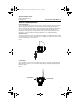
00825-0100-4648_CC.fm Page 4 Monday, February 13, 2012 12:48 PM Quick Installation Guide Rosemount 648 Wireless 00825-0100-4648, Rev CC February 2012 Field Communicator Connections The Power Module needs to be installed in the device for the Field Communicator to interface with the 648. Field communication with this device requires a Field communicator using the correct 648 wireless DD. The correct DD for the available protocol should be selected.
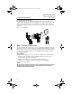
00825-0100-4648_CC.fm Page 5 Monday, February 13, 2012 12:48 PM Quick Installation Guide 00825-0100-4648, Rev CC February 2012 Rosemount 648 Wireless STEP 1 CONTINUED... 5. Close the housing cover and tighten to safety specification. Always ensure a proper seal by installing the electronics housing covers so that metal touches metal, but do not over tighten. 6. Position the antenna such that it is vertical, either straight up or straight down. The antenna should be approximately three ft.
00825-0100-4648_CC.fm Page 6 Monday, February 13, 2012 12:48 PM Quick Installation Guide Rosemount 648 Wireless 00825-0100-4648, Rev CC February 2012 STEP 1 CONTINUED... 6. Close the housing cover and tighten to safety specification. Always ensure a proper seal by installing the electronics housing covers so that metal touches metal, but do not over tighten. 7. Position the antenna such that it is vertical, either straight up or straight down.
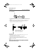
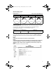
00825-0100-4648_CC.fm Page 7 Monday, February 13, 2012 12:48 PM Quick Installation Guide 00825-0100-4648, Rev CC February 2012 Searching for Network Rosemount 648 Wireless Joining Network Connected with 1 Parent Connected with 2 Parents netwk netwk netwk netwk A -srch JOING 1PARNT 2PARNT Field Communicator To verify operation using a Field Communicator, refer to the Fast Key Sequence in Table 1. Select the Radio State parameter to verify operation.
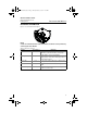
00825-0100-4648_CC.fm Page 8 Monday, February 13, 2012 12:48 PM Quick Installation Guide 00825-0100-4648, Rev CC February 2012 Rosemount 648 Wireless AMS™ Suite: Intelligent Device Manager When the device has joined the network, it will appear in the Device Manager as illustrated below.
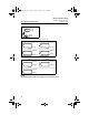
00825-0100-4648_CC.fm Page 9 Monday, February 13, 2012 12:48 PM Quick Installation Guide 00825-0100-4648, Rev CC February 2012 Rosemount 648 Wireless REFERENCE INFORMATION Figure 5. Rosemount 648 Terminal Diagram NOTE: In order to communicate with a Field Communicator, the device must be powered by connecting the Power Module. Table 2.
00825-0100-4648_CC.fm Page 10 Monday, February 13, 2012 12:48 PM Quick Installation Guide 00825-0100-4648, Rev CC February 2012 Rosemount 648 Wireless Figure 6. Series 65, Series 68, Series 78, and 58C Lead Wire Configurations Single Element White (1) White (2) Red (3) Red (4) Figure 7. Series 183 Thermocouple Lead Wire Configurations Type J Type E + White (2) + Purple (2) – Red (3) Type K – Red (3) Type T + Yellow (2) + Blue (2) – Red (3) – Red (3) Figure 8.
00825-0100-4648_CC.fm Page 11 Monday, February 13, 2012 12:48 PM Quick Installation Guide 00825-0100-4648, Rev CC February 2012 Rosemount 648 Wireless PRODUCT CERTIFICATIONS Approved Manufacturing Locations Rosemount Inc. – Chanhassen, Minnesota, USA Emerson Process Management GmbH & Co. - Karlstein, Germany Emerson Process Management Asia Pacific Private Limited - Singapore European Union Directive Information The most recent revision of the European Union Declaration of Conformity can be found at www.
00825-0100-4648_CC.fm Page 12 Monday, February 13, 2012 12:48 PM Quick Installation Guide Rosemount 648 Wireless 00825-0100-4648, Rev CC February 2012 Hazardous Locations Certificates North American Certifications Factory Mutual (FM) Approvals I5 FM Intrinsically Safe, Non-incendive Intrinsically Safe for Class I/II/III, Division 1, Groups A, B, C, D, E, F, and G.
00825-0100-4648_CC.fm Page 13 Monday, February 13, 2012 12:48 PM Quick Installation Guide 00825-0100-4648, Rev CC February 2012 Rosemount 648 Wireless European Certifications I1 ATEX Intrinsic Safety Certificate No.: Baseefa07ATEX0011X Ex ia IIC T5 (Ta = -60 °C to 40 °C) Ex ia IIC T4 (Ta = -60 °C to 70 °C) IP66/IP67 II 1G Special Conditions for Safe Use (X) 1. The antenna may present a potential electrostatic ignition hazard and must not be rubbed or cleaned with a dry cloth. 2.
00825-0100-4648_CC.fm Page 14 Monday, February 13, 2012 12:48 PM Quick Installation Guide Rosemount 648 Wireless 00825-0100-4648, Rev CC February 2012 Table 4. Sensor Parameters Sensor Uo = 6.6 V Io = 26 mA Po = 42.6 mW Co = 10.9 uF Lo = 500 mH Japanese Certifications I4 TIIS Intrinsic Safety Ex ia IIC T4 Certificate TC18194. Various configurations available. Consult factory for certified assemblies. China (NEPSI) Certifications I3 China Intrinsic Safety Certificate No.
00825-0100-4648_CC.fm Page 15 Monday, February 13, 2012 12:48 PM Quick Installation Guide 00825-0100-4648, Rev CC February 2012 Radio Power Label - see Figure 9 - indicates output power configuration of the radio. Devices with this label are configured for output power less than 10 mW e.i.r.p. At time of purchase, the customer must specify ultimate country of installation and operation. Rosemount 648 Wireless Figure 9.
00825-0100-4648_CC.fm Page 16 Monday, February 13, 2012 12:48 PM Quick Installation Guide Rosemount 648 Wireless Figure 10.
00825-0100-4648_CC.
00825-0100-4648_CC.