
Installation guide


Quick Installation Guide
00825-0100-4648, Rev CC
February 2012
Rosemount 648 Wireless
4
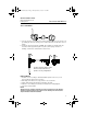
Field Communicator Connections
The Power Module needs to be installed in the device for the Field Communicator to
interface with the 648. Field communication with this device requires a Field communicator
using the correct 648 wireless DD. The correct DD for the available protocol should be
selected. Refer to Figure 3 below for instructions for connection of the Field Communicator
to the 648.
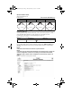
Figure 3. Connection Diagram
STEP 1: PHYSICAL INSTALLATION
The Rosemount 648 can be installed in one of two configurations: Direct Mount, where the
thermocouple or sensor is connected directly to the 648 housing’s conduit entry, or Remote
Mount, where the thermocouple or sensor is mounted separate from the 648 housing, then
connected to the 648 using conduit. Choose the installation sequence that corresponds to
the mounting configuration.
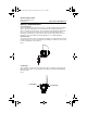
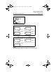
Direct Mount
The direct mount installation should not be used when installing with a Swagelok
®
fitting.
1. Install the sensor according to standard installation practices. Be sure to use an
approved thread sealant on all connections.
2. Attach the 648 housing to the sensor using the threaded conduit entry.
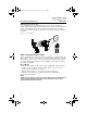
3. Attach the sensor wiring to the terminals as indicated on the wiring diagram.
4. Connect the Power Module.
NOTE:
Wireless devices should be powered up in order of proximity from the Smart Wireless
Gateway, beginning with the closest device to the Gateway. This will result in a
simpler and faster network installation.
COMM
P/N 00753-9200-0020
1
2
3
4
00825-0100-4648_CC.fm Page 4 Monday, February 13, 2012 12:48 PM