
Installation guide


Quick Installation Guide
00825-0100-4648, Rev CC
February 2012
Rosemount 648 Wireless
9
REFERENCE INFORMATION
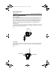
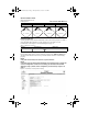
Figure 5. Rosemount 648 Terminal Diagram
NOTE:
In order to communicate with a Field Communicator, the device must be powered by
connecting the Power Module.
Table 2. 648 Fast Key Sequence
Function Key Sequence Menu Items
Device Information
1, 3, 5, 2
Tag, Date, Descriptor, Message, Model, Model
Number I, Model Number II, Model Number III,
Write Protect, Revision Numbers, Transmitter
Serial Numbers, Device ID, Distributor
PV Range Values 1, 3, 4, 1 Lower Range Point, Upper Range Point, Unit,
Apply Values, Lower Sensor Limit, Upper Sensor
Limit, Minimum Span
Sensor Trim 1, 2, 2, 1 Lower Sensor Trim, Upper Sensor Trim, Recall
Factory Trim, Active Calibrator
Wireless 1, 3, 3 Smart Power, Network ID, Set Join Key, Radio
State
Sensor Configuration 1, 3, 2, 1 Sensor Configuration, Temp Sensor Setup, Cal
VanDusen, Sensor S/N
00825-0100-4648_CC.fm Page 9 Monday, February 13, 2012 12:48 PM