READ AND SAVE THESE INSTRUCTIONS BATON ROUGE ™ Ceiling Fan Owner's Manual Model Numbers CF3200AWL00 CF3200DBZ00 Summer White w/Latte Highlights Distressed Bronze Net Weight: Part No. F40BP73500000 26.0 Lbs. Form No. BP7350 U.L. Model No.
! WARNING WARNING: To avoid fire, shock, and serious personal injury, follow these instructions. Safety Instructions 1. Read your owner’s manual carefully and keep it for future reference 2. Before servicing or cleaning unit, switch power off at service panel and lock service panel disconnecting means to prevent power from being switched on accidentally. When the service disconnecting means cannot be locked, securely fasten a warning device, such as a tag, to the service panel. 3.
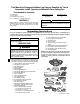
This Manual Is Designed to Make it as Easy as Possible for You to Assemble, Install, Operate and Maintain Your Ceiling Fan Tools Needed for Assembly Installed Wire Length Up to 50 ft. 50-100 ft. One stepladder One wire stripper One Phillips head screwdriver Four 15-watt (max.) candelabra base bulbs MATERIALS WARNING ! Wiring outlet box and box connectors must be of type required by the local code. The minimum wire would be a 3-conductor (2-wire with ground) of the wire size, to right: Wire Size A.W.G.
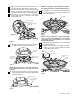
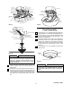
IMPORTANT: Your ceiling fan is supplied with an SW116 Fan/Light Wall Control (transmitter) and a remote control SW105 Receiver which mounts under the ceiling cover. This system allows you to regulate your ceiling fan speed, airflow direction, and light intensity. An optional Emerson Electric SR110 Remote Control may also be used. Ceiling Fan Assembly Procedures 1. Place the flange assembly onto the bottom of the blade assembly. Place the flange medallion assembly into the four holes of the blade assembly.
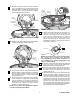
7. Remove the wire connector from the white wire of the switch housing plate. Retain for the next step. 8. Connect the white wire from the switch housing plate to the white wire of the switch housing, using the wire connector previously removed (Figure 3). 9. Connect the 9-pin connector from the switch housing plate to the 9-pin connector of the switch housing (Figure 3). NOTE: If installing an optional Emerson light kit, follow the instructions provided with the light kit. 12.
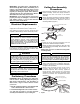
15. Securely connect the white fan one-pin connector wire to the white one-pin connector wire from the light kit assembly. Connect the yellow fan one-pin connector wire to the yellow light kit assembly one-pin connector wire (Figure 8). LIGHT KIT ASSEMBLY SCREW (3) LIGHT KIT ASSEMBLY NOTCHED HOLE KEYHOLE SLOTS LIGHT KIT ASSEMBLY YELLOW LIGHT KIT ASSEMBLY WIRE NOTCHED HOLE WHITE LIGHT KIT ASSEMBLY WIRE ONE-PIN CONNECTOR YELLOW FAN WIRE Figure 10 WHITE FAN WIRE 19.
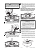
25. Slide the motor cover over the downrod and rotate the cover until the threaded studs protrude. Install one lockwasher (supplied) and one knurled knob (supplied) onto each threaded stud to secure the cover to the motor. All wires and wire connectors must be enclosed under the motor cover (Figure15). NOTE: Lightly snug the knurled knob and make sure the wires and wire connectors are completely inside the motor coupling cover and not pinched between the motor coupling cover and the motor.
28. The blue, black, white, and yellow leads exiting the downrod are 80-inches long. Before installing the fan, measure up approximately 6 to 9-inches above the ball/downrod assembly. Cut off excess leads and strip back insulation 1/2-inch from end of leads. 3. Slide the assembled decorative scroll over the 12” downrod and position each scroll leg on the decorative light kit ring (Figure 19). Secure each of the four decorative scroll legs using four #8-32 x 15mm flat head screws (supplied). 29.
! WARNING ! Failure to seat tab in groove could cause damage to electrical wires and possible shock or fire hazard. To reduce the risk of fire, electric shock, or personal injury, mount fan to outlet box marked “Acceptable for Fan Support”, and use screws supplied with outlet box. Most outlet boxes commonly used for support of light fixtures are not acceptable for fan support and may need to be replaced. Consult a qualified electrician if in doubt.
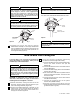
OUTLET BOX BLACK SUPPLY WIRE HANGER BRACKET BLACK FAN WIRE HANGER BRACKET GROUND WIRE (GREEN) OUTLET BOX BLACK/WHITE RECEIVER WIRE BLUE FAN WIRE HANGER BALL GROUND WIRE (GREEN) HANGER BRACKET BLUE RECEIVER WIRE 1-1/4" THREADED STUDS (2) OPEN PORTION OF RECEIVER HERE SUPPLY GROUND WIRE (GREEN OR BARE) RECEIVER YELLOW FAN WIRE YELLOW RECEIVER WIRE RECEIVER BLACK RECEIVER WIRE WHITE SUPPLY WIRE WHITE RECEIVER WIRE CEILING COVER WHITE FAN WIRE CEILING COVER WIRE CONNECTOR Figure 23 Figure
Setting Operating Frequency of Wall Control and Receiver (Figure 27) Installation of Wall Control ! Your wall control and receiver have code switches which must be set in one of 16 possible code combinations. The four levers (numbered 1, 2, 3, and 4) on the switches are factory-set in the ON (up) position. Change the switch settings as follows: WARNING Turning off wall switch is not sufficient. To avoid possible electrical shock, be sure electricity is turned off at the main fuse or circuit breaker box.
5. To turn the lights on and off, press and release the U/L (uplight) button or the D/L (downlight) button (if downlight kit is added to fan). The lights will turn on at the light level previously set (see Step 4). Red light turns on when any button is pressed. If the light does not come on, replace your battery. Operating Your Ceiling Fan IMPORTANT Fan installation must be completed, including the installation of the fan blades, before testing of the remote control.
Accessories Attaching Light Kit ! 1. Ceiling Fan Light Kits (see store or catalog). WARNING 2. Ceiling Fan/Light Controls (see store or catalog). To avoid possible electrical shock, be sure electricity is turned off at the main fuse box before wiring. 3. Downrod Extension Kits (see store or catalog). To install an accessory light kit, remove the three screws securing the switch cup assembly to the fan, remove the switch cup assembly, and disconnect the connector.
Repair Parts 1 2 30 9 HIHI LIGHT MED MED LOW LOW 6 REV REV FAN OFF 3 31 29 8 34 17 16 10 11 34 23 33 15 32 9 5 19 11 10 18 4 20 22 7 129 10-32 x 10mm PAN HEAD SCREW (4 Per Blade) 21 26 BLADE FLANGE ASSEMBLY 24 FLANGE MEDALLION 8 25 14 13 27 28 14 U.L. Model No.
Repair Parts Listing Model No. Key No. Description CF3200AWL00 CF3200DBZ00 * 1 2 3 * 4 5 6 7 8 9 10 11 12 13 14 15 16 17 Hanger Pack, Consisting of: Hanger Bracket Hanger Ball Downrod - 12” Parts Bag Containing: Pin, Clevis (1) Clip, Hairpin (1) Wire Connector, 12 Ga. (5) Setscrew, 5/16-18 x 1/4” (1) Setscrew Wrench, Hex.
LIMITED WARRANTY What The Warranty Covers: This warranty covers the motor and the other components and accessories of your Emerson Electric Co. ceiling fan against all defects in workmanship and materials. You must be the original purchaser or user of the product to be covered. What The Period Of Coverage Is: As it applies to the motor, this warranty will last for a lifetime from the date you purchased your ceiling fan.