BP7357 CF180 BRIDGETON 9/19/07 11:21 AM Page 1 READ AND SAVE THESE INSTRUCTIONS BRIDGETON™ Ceiling Fan Owner's Manual Model Numbers CF180AP00 CF180GES00 Antique Pewter with Natural Cherry/Mahogany Blades Golden Espresso with Teak/Natural Pine Blades Net Weight: Part No. F40BP73570001 30.9 Lbs. Form No. BP7357-1 U.L. Model No.
BP7357 CF180 BRIDGETON 9/19/07 11:21 AM ! Page 2 WARNING WARNING: To avoid fire, shock, and serious personal injury, follow these instructions. Safety Instructions 1. Read your owner’s manual carefully and keep it for future reference. 2. Before servicing or cleaning unit, switch power off at service panel and lock service panel disconnecting means to prevent power from being switched on accidentally.
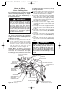
BP7357 CF180 BRIDGETON 9/19/07 11:21 AM Page 3 This Manual Is Designed to Make it as Easy as Possible for You to Assemble, Install, Operate and Maintain Your Ceiling Fan 1. Open styrofoam unit containing fan. Remove top half of styrofoam unit. Remove parts and check to see that you have received the following parts: Tools Needed for Assembly One Phillips head screwdriver One wire stripper Six wire connectors (supplied) Three 60-watt (max.
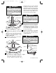
BP7357 CF180 BRIDGETON 9/19/07 11:21 AM Page 4 Preset Memory Feature 2. Remove the fan motor and housing assembly from the protective plastic bag. Place the fan assembly into the lower foam pad with the bottom of the motor facing up. The lower foam pad serves as a holder for the fan during the first stages of assembly. Your remote control receiver is equipped with a preset memory feature.
BP7357 CF180 BRIDGETON 9/19/07 11:21 AM 2. Slide the four switch levers on the code switch to your choice of ON (up) or down positions. Use a ball-point pen or small screwdriver and slide the levers firmly up or down. 3. In the receiver (Figure 1), slide the four switch levers to the same positions as set in the transmitter. Make sure the levers on both switches are in the same positions, otherwise the fan will not operate. 4.
BP7357 CF180 BRIDGETON ! 9/19/07 11:21 AM through the two holes in the downrod and align the hanger ball so the pin is captured in the groove in the top of the hanger ball. Pull the hanger ball up tight against the pin and securely tighten the setscrew in the hanger ball. A loose setscrew could create fan wobble. WARNING It is critical that the clevis pin in the motor coupling is properly installed and the setscrews securely tightened.
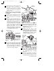
BP7357 CF180 BRIDGETON 9/19/07 11:21 AM 8. Turn the fan motor and housing assembly upside down in preparation for mounting the fan blade assemblies. Remove and discard the three shipping retainers securing the motor hub in the motor housing. NOTE: Take care not to scratch the fan housing when installing the blade assemblies. 9. Insert a 1/4-20 x 11mm pan head screw with lockwasher (supplied) into each of the recessed holes in one of the blade flanges. 10.
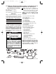
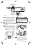
BP7357 CF180 BRIDGETON 9/19/07 11:21 AM Page 8 How to Hang Your Ceiling Fan ! WARNING OUTLET BOX The fan must be hung with at least 7' of clearance from floor to blades (Figure 9). TWO SCREWS SUPPLIED WITH OUTLET BOX CEILING HANGER BRACKET TAB Figure 10 2. Carefully lift the fan and seat the hanger ball/downrod assembly on the hanger bracket that was just attached to the outlet box (Figure 11). Be sure the groove in the ball is lined up with the tab on the hanger bracket (Figure 10).
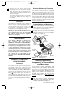
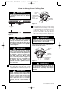
BP7357 CF180 BRIDGETON 9/19/07 11:21 AM How to Wire Your Ceiling Fan is visible at the wire connectors, except for the ground wire. 2. Refer to Figure 12 and 13 and connect the receiver wires to the supply wires and the fan motor wires as follows: a. Securely connect the green grounding wires from the hanger ball and the hanger bracket to the supply grounding conductor (this may be a bare wire or a wire with green insulation). b.
BP7357 CF180 BRIDGETON TO 120VOLT SUPPLY 9/19/07 11:21 AM Page 10 STANDARD ON-OFF WALL SWITCH OR OPTIONAL SW101 WALL CONTROL BLACK BLACK (HOT) BLACK WHITE WHITE WHITE GROUND RED TWO-CONDUCTOR CABLE (WITH GROUND) BLUE BLACK BLUE WHITE GREEN WIRE (GROUND) FROM HANGER BALL AND HANGER BRACKET Figure 13 HANGER BALL 3. Push the wires and connectors up into the outlet box while inserting the receiver fully into the hanger bracket. Position the antenna wire on top of the receiver. 4.
BP7357 CF180 BRIDGETON 9/19/07 11:21 AM 9. Grasp the lower ring assembly and raise it up and over the ring rods of the adapter assemlby (Figure 16). Position the ring assembly of that the ring assembly arms protrude through the holes at the end of the ring rods. Secure the ring asembly in the ring rods using the six ring screws. RING SCREWS (6) Page 11 button is held down. When the light is at the desired brightness, release the button. 5. To turn the light on and off, press and release the button.
BP7357 CF180 BRIDGETON 9/19/07 11:21 AM Page 12 Maintenance Accessories IMPORTANT CARE INSTRUCTIONS for your Ceiling Fan 1. Downrod Extension Kits (see store or catalog). Periodic cleaning of your new ceiling fan is the only maintenance that is needed. 2. Ceiling Fan Controls (see store or catalog). When cleaning, use only a soft brush or lint free cloth to avoid scratching the finish.
BP7357 CF180 BRIDGETON 9/19/07 11:21 AM Page 13 WARNING: FOR YOUR OWN SAFETY TURN OFF POWER AT FUSE BOX ! OR CIRCUIT BREAKER BEFORE TROUBLE SHOOTING YOUR FAN. Trouble Shooting TROUBLE 1. Fan will not start. PROBABLE CAUSE 1. Fuse or circuit breaker blown. 2. Loose power line connections to the fan, or loose wire connections in the switch housing. 3. Wall switch is off. 4. Defective battery in remote control transmitter. 5.
BP7357 CF180 BRIDGETON 9/19/07 11:21 AM Page 14 Repair Parts 1 2 25 3 5 MED HI LOW OFF 24 4 14 7 6 8 10 11 15 9 17 16 12 18 19 13 20 21 22 23 14 U.L. Model No.
BP7357 CF180 BRIDGETON 9/19/07 11:21 AM Page 15 Repair Parts Listing Part Numbers Key No. Description Model No. CF180AP00 Model No.
BP7357 CF180 BRIDGETON 9/19/07 11:21 AM Page 16 LIMITED WARRANTY What The Warranty Covers: This warranty covers the motor and the other components and accessories of your Emerson ceiling fan against all defects in workmanship and materials. You must be the original purchaser or user of the product to be covered. What The Period Of Coverage Is: As it applies to the motor, this warranty will last for the lifetime of your ceiling fan.