
Owner`s manual


3
THIS FAN IS SUITABLE FOR DAMP LOCATIONS
SUCH AS COVERED PORCHES, COVERED PATIOS, AND COVERED
DECKS...ANYWHERE THERE IS A ROOF OVERHEAD.
This Manual is Designed to Make it as Easy as Possible for You to
Assemble, Install, Operate and Maintain Your Ceiling Fan
Do not install or use fan if any part is
damaged or missing. Call Toll-Free:
1-800-654-3545
!
WARNING
This product is designed to use only
those parts supplied with this product
and/or any accessories designated
specifically for use with this product by
Emerson Electric Co. Substitution of
parts or accessories not designated for
use with this product by Emerson Electric
Co. could result in personal injury or
property damage.
!
WARNING
Tools Needed for Assembly
One Phillips head screwdriver
One wire stripper
One stepladder
Materials
Wiring, outlet box and box connectors
must be of type required by the local code.
The minimum wire shall be a 3-conductor
(2-wire with ground) of the following sizes:
Installed Wire Length Wire Size A.W.G.
Up to 50 ft. 14
50-100 ft. 12
Before assembling your ceiling fan, refer
to section on proper method of wiring
your fan (Page 9). If you feel you do not
have enough wiring knowledge or
experience, have your fan installed by a
licensed electrician.
!
WARNING
Unpacking Instructions
For your convenience, check-off boxes are provided next to each step. As each
step is completed, place a check mark in the box. This will insure that all steps
have been completed and will be helpful in finding your place should you be
interrupted.
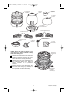
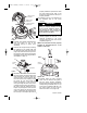
NOTE: If you are uncertain of part
description, refer to exploded view
illustration.
a. Fan motor assembly
b. One motor cover
c. One coupling cover
d. One ceiling cover
e. One switch adapter plate
f. Four blade flanges
g. Four blade medallions
h. One switch cover plate
i. One hanger bracket
j. One hanger ball/downrod assembly
k. One loose parts bag containing:
1. One clevis pin
2. One hairpin clip
3. Two #8-32 x 1-1/4” threaded studs
4. Two #8 external tooth lockwashers
5. Two #8-32 knurled knobs
6. Thirteen #10-32 x 3/4” oval head
blade screws
7. Five wire connectors
8. One 3/16” hex wrench
9. One chain coupler
10. One chain pendant
11. Nine #8-32 x 5/8” flat head
flange screw
12. One 5/16-18 x 1/4” setscrew
13. Three #8-32 x 1/4” flat head screws
14. One pendant
1. Open carton containing fan. Remove
top half of styrofoam unit. Remove
parts, placing all carton contents on a
soft protective surface to prevent
scratching the painted or plated
finishes, and check to see that you
have received the following parts:
Model No.: CF3600
BP7384 Camden, CF3600 3/12/09 12:37 PM Page 3