
Owner`s manual


6
Model No.: CF3600
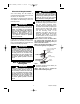
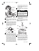
FLANGE
MOTOR HUB
MOUNTING HOLE
#8-32 x 5/8" FLAT HEAD SCREW
(2 per flange/blade assembly)
BLADE
ASSEMBLY
Figure 2
Note: Be sure the flange screws on the
blade assembly are facing down for
correct installation into the motor hub.
3. Insert the blade flange into one of the
mounting holes in the motor hub
(Figure 2). Align the flange with the slot
in the motor assembly. Insert one #8-32
x 5/8” flat head screw (supplied) into
one of the flange mounting holes; do
not fully tighten. Install the second
screw in the same manner; tighten both
screws securely.
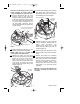
7. Securely engage the 3-pin connector
from the fan motor assembly with the
switch cover connector. The
connectors are keyed and must be
mated correctly before they can be
engaged (Figure 5).
8. Slide the pull chain through the chain
busing located on the side of the switch
cover.
9. Position the switch cover assembly
onto the fan motor switch cover adapter
plate. Align the switch cover assembly
switches with the clearance notches in
the motor assembly switch cover
adapter plate. Secure the cover using
three #8-32 x 1/4” flat head screws
(supplied).
NOTE: Do not pinch wires between the
fan motor assembly and switch cover
assembly.
NOTE: Take care not to scratch fan
housing when installing blades.
4. Repeat assembly instructions for the
remaining three blade assemblies.
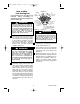
PAN HEAD
SCREW (3)
MOTOR
FLANGE
Figure 3
PAN HEAD SCREW (3)
SWITCH
ADAPTER
PLATE
FAN MOTOR
ASSEMBLY
Figure 4
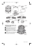
5. Remove and retain one of the three
pan head screws from the motor flange
(Figure 3); loosen the other two pan
head screws three or four turns.
Position the switch adapter plate on the
motor flange so that the two screws
mate with the two keyhole slots in the
adapter (Figure 4).
6. Turn the switch adapter plate clockwise
and tighten both screws (Figure 4).
Reinstall the other pan head screw in
the remaining hole in the adapter.
BP7384 Camden, CF3600 3/12/09 12:37 PM Page 6