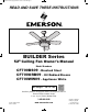
BP7312-4 CF700.qxp_ BP7312 2/27/15 5:13 PM Page 1 READ AND SAVE THESE INSTRUCTIONS BUILDER Series 52” Ceiling Fan Owner's Manual Model Numbers CF700BS09 - Brushed Steel CF700ORB09 - Oil Rubbed Bronze CF700WW09 - Appliance White Net Weight: 14.4 Lbs. Questions, problems, missing parts: Before returning to the store call Emerson Electric Customer Service 8 a.m. - 6 p.m., Eastern, Monday-Friday Part No. F40BP73120004 Revision: 150226 1-800-654-3545 www.emersonfans.
BP7312-4 CF700.qxp_ BP7312 2/27/15 5:13 PM Page 2 Table of Contents Section Page Safety Instructions . . . . . . . . . . . . . . . . . . . . . . . . . . . .2 1. Unpacking Instructions . . . . . . . . . . . . . . . . . . . . .3-4 2. Electrical Requirements . . . . . . . . . . . . . . . . . . . . .4 3. Ceiling Fan Assembly . . . . . . . . . . . . . . . . . . . .5-10 4. How to Hang Your Ceiling Fan . . . . . . . . . . . .11-12 5. How to Wire Your Ceiling Fan . . . . . . . . . . . . .13-15 6.
BP7312-4 CF700.qxp_ BP7312 2/27/15 5:13 PM Page 3 1. Unpacking Instructions WARNING ! PACKAGE CONTENTS Do not install or use fan if any part is damaged or missing. Call Toll-Free for replacement parts: 1-800-654-3545 Part WARNING ! This product is designed to use only those parts supplied with this product and/or any accessories designated specifically for use with this product by Emerson Electric Co.
BP7312-4 CF700.qxp_ BP7312 2/27/15 5:13 PM Page 4 1. Unpacking Instructions (Continued) This Manual Is Designed to Make it as Easy as Possible for You to Assemble, Install, Operate and Maintain Your Ceiling Fan Tools Needed for Assembly One Phillips head screwdriver One Standard screwdriver Materials ! Before assembling your ceiling fan, refer to section on proper method of wiring your fan (page 12).
BP7312-4 CF700.qxp_ BP7312 2/27/15 5:13 PM Page 5 3.1 3. Ceiling Fan Assembly ! WARNING Turning off wall switch is not sufficient. To avoid possible electrical shock, be sure electricity is turned off at the main fuse box before wiring. All wiring must be in accordance with National and Local codes and the ceiling fan must be properly grounded as a precaution against possible electrical shock.
BP7312-4 CF700.qxp_ BP7312 2/27/15 5:13 PM Page 6 3. Ceiling Fan Assembly 3.4 (Continued) DOWNROD Loosen the two setscrews in the motor coupling. Place the hanger ball/4.5” downrod assembly into the motor coupling, aligning the clevis pin holes in the downrod with the holes in the motor coupling (Figure 3). CLEVIS PIN The clevis pin must go through the holes in the motor coupling and the holes in the downrod.
BP7312-4 CF700.qxp_ BP7312 2/27/15 5:13 PM Page 7 3.6 3. Ceiling Fan Assembly (Continued) The fan comes with blue, black and white leads that are 42” long. 6 to 9 INCHES Measure up approximately 6 to 9-inches above top of hanger ball/4.5” downrod assembly (Figure 5). HANGER BALL/ DOWNROD ASSEMBLY Cut off excess leads and strip back insulation 1/2-inch from end of leads. Figure 5 3.
BP7312-4 CF700.qxp_ BP7312 2/27/15 5:13 PM Page 8 3. Ceiling Fan Assembly 3.9 (Continued) M5 x 6mm WASHER HEAD BLADE SCREW (3) Mount the blade flange to the fan blade using three M5 x 6mm washer head screws (supplied) (Figure 8). Repeat this procedure for other four fan blades and blade flanges. ! FAN BLADE WARNING To reduce the risk of personal injury, do not bend the blade flange when installing the blade flanges, balancing the blades or cleaning the fan.
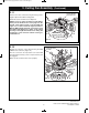
BP7312-4 CF700.qxp_ BP7312 2/27/15 5:14 PM Page 9 3.11 3. Ceiling Fan Assembly (Continued) SWITCH HOUSING MOUNTING PLATE Remove the three switch housing mounting screws (Figure 10) from the switch housing plate. NOTE: If you are using an Emerson light fixture with your fan. Remove the screw plug from the bottom of the switch housing cover and install the light in accordance with the light kit Owner's Manual.
BP7312-4 CF700.qxp_ BP7312 2/27/15 5:14 PM Page 10 3.13 3. Ceiling Fan Assembly Position the switch housing assembly on the switch housing plate and align the holes in the switch housing assembly with the holes in the plate. (Continued) SWITCH HOUSING ASSEMBLY Secure the switch housing assembly by reinstalling the three mounting screws (previously removed) (Figure 12). NOTE: Do not pinch wires between the switch housing assembly and the switch housing plate.
BP7312-4 CF700.qxp_ BP7312 2/27/15 5:14 PM Page 11 ! 4. How to Hang Your Ceiling Fan WARNING CEILING The fan must be hung with at least 7' of clearance from floor to blades (Figure 12). AT LEAST 7' FLOOR Figure 13 ! WARNING The outlet box and joist must be securely mounted and capable of supporting at least 50 lbs. Use only a U.L. outlet box listed as “Acceptable for Fan Support of 22.7 kg. (50 lbs.) or less”.
BP7312-4 CF700.qxp_ BP7312 2/27/15 5:14 PM Page 12 4.2 4. How to Hang Your Ceiling Fan (Continued) NOTE: SUPPLY WIRES AND FAN WIRES OMITTED FOR CLARITY. Carefully lift the fan and seat the hanger ball/ downrod assembly on the hanger bracket that was just attached to the outlet box (Figure 15). Be sure the groove in the ball is engaged with the anti-rotation tab on the hanger bracket (Figure 15).
BP7312-4 CF700.qxp_ BP7312 2/27/15 5:14 PM Page 13 5. How to Wire Your Ceiling Fan If you feel that you do not have enough electrical wiring knowledge or experience, have your fan installed by a licensed electrician. ! WARNING GROUND CONDUCTOR SUPPLY To avoid possible electrical shock, be sure electricity is turned off at the main fuse box before wiring. NOTE: If you are not sure if the outlet box is grounded, contact a licensed electrician for advice, as it must be grounded for safe operation.
BP7312-4 CF700.qxp_ BP7312 2/27/15 5:14 PM Page 14 5.3 5. How to Wire Your Ceiling Fan (Continued) Securely connect the fan motor black wire and blue wires to the supply black (hot) wire using wire connector (supplied) (Figure 18). FAN MOTOR BLACK WIRE SUPPLY BLACK (HOT) LISTED WIRE CONNECTOR FAN MOTOR BLUE WIRE Figure 18 5.
BP7312-4 CF700.qxp_ BP7312 2/27/15 5:14 PM Page 15 5.5 5. How to Wire Your Ceiling Fan (Continued) Screw the two threaded studs (supplied) into the tapped holes in the hanger bracket (Figure 20). THREADED STUDS (2) Figure 20 5.6 Lift the ceiling cover up to the threaded studs and turn until studs protrude through the holes in the ceiling cover (Figure 21). 5.
BP7312-4 CF700.qxp_ BP7312 2/27/15 5:14 PM Page 16 6. Using Your Ceiling Fan 6.1 Restore electrical power to the outlet box by turning the electricity on at the main fuse box. Check the operation of the fan by gently pulling on the pull chain switch. All fans are shipped from the factory with the reversing switch positioned to the “left” circulate air downward.
BP7312-4 CF700.qxp_ BP7312 2/27/15 5:14 PM Page 17 7. Maintenance IMPORTANT CARE INSTRUCTIONS for your Ceiling Fan ! WARNING ! WARNING Do not use water when cleaning your ceiling fan. It could damage the motor or the blades and create the possibility of an electrical shock. Periodic cleaning of your new ceiling fan is the only maintenance that is needed. When cleaning, use only a soft brush or lint free cloth to avoid scratching the finish.
BP7312-4 CF700.qxp_ BP7312 2/27/15 5:14 PM Page 18 9. Repair Parts PARTS BAG 1 2 9 10 3 9 11 12 4 13 11 10 14 14 13 15 16 16 17 6 5 18 15 8 7 17 18 U.L. Model No.
BP7312-4 CF700.qxp_ BP7312 2/27/15 5:14 PM Page 19 9. Repair Parts Listing Model Numbers Key No. Description CF700BS09 CF700ORB09 CF700WW09 * Hanger Ball Assembly, Consisting of: 760750-24 760750-48 760750-3 1 Hanger Bracket (1) — — — 2 Hanger Ball (1) — — — 3 4.
BP7312-4 CF700.qxp_ BP7312 2/27/15 5:14 PM Page 20 10. Trouble Shooting ! WARNING: FOR YOUR OWN SAFETY TURN OFF POWER AT FUSE BOX OR CIRCUIT BREAKER BEFORE TROUBLE SHOOTING YOUR FAN. TROUBLE 1. Fan will not start. PROBABLE CAUSE SUGGESTED REMEDY 1. Reversing switch in neutral position. 2. Fuse or circuit breaker blown. 2. Fan sounds noisy. 3. Fan wobbles or shakes excessively. 3. Loose power line connections to the fan, or loose switch wire connections in the switch housing. 1.
BP7312-4 CF700.qxp_ BP7312 2/27/15 5:14 PM Page 21 11. Energy Efficient Use of Ceiling Fans Using the Ceiling Fan Year Round. In the summer, use the ceiling fan in the counter-clockwise direction. The airflow produced by the ceiling fan creates a windchill effect, making you "feel" cooler. Select a fan speed that provides a comfortable breeze, lower speeds consume less energy. In the winter, reverse the motor and operate the ceiling fan at low speed in the clockwise direction.
BP7312-4 CF700.qxp_ BP7312 2/27/15 5:14 PM Page 22 Notes 22 U.L. Model No.
BP7312-4 CF700.qxp_ BP7312 2/27/15 5:14 PM Page 23 Emerson Air Comfort Ceiling Fan Limited Warranty What The Limited Warranty Covers: This limited warranty is offered by Air Comfort Products division of Emerson Electric Co.
BP7312-4 CF700.qxp_ BP7312 2/27/15 5:14 PM Page 24 Air Comfort Products DIVISION OF EmErSON ElEctrIc cO. 8100 W. Florissant • St. louis, mO 63136 Questions, problems, missing parts: Before returning to the store call Emerson Electric Customer Service 8 a.m. - 6 p.m., Eastern, Monday-Friday 1-800-654-3545 www.emersonfans.com Retain this manual for future use. Part No. F40BP73120004 Revision: 150226 Printed in China 02/15 Form No. BP7312-4 U.L. Model No.
BP7312-4 CF700.qxp_ BP7312 2/27/15 5:14 PM Page 25 LEA Y GUARDE ESTAS INSTRUCCIONES Serie BUILDER Manual del usuario para ventiladores de techo de 52 pulgadas CF700BS09 - Acero cepillado CF700ORB09 - Bronce frotado con aceite CF700WW09 - Blanco electrodoméstico Números de modelo Peso neto: 14,4 lb. Preguntas, problemas, piezas faltantes: Antes de devolver el producto a la tienda, llame a Servicio al Cliente de Emerson Electric 8 a.m. a 6 p.m., Hora del Este, lunes a viernes 1-800-654-3545 www.
BP7312-4 CF700.qxp_ BP7312 2/27/15 5:14 PM Page 26 Índice Sección Página 7. Mantenimiento . . . . . . . . . . . . . . . . . . . . . . . . . . . . . . . . . . . . . .41 8. Accesorios . . . . . . . . . . . . . . . . . . . . . . . . . . . . . . . . . . . . . . . . .41 9. Piezas de repuesto . . . . . . . . . . . . . . . . . . . . . . . . . . . . . . . .42-43 10. Resolución de problemas . . . . . . . . . . . . . . . . . . . . . . . . . . . . .44 11. Uso energéticamente eficiente de los ventiladores de techo . .
BP7312-4 CF700.qxp_ BP7312 2/27/15 5:14 PM Page 27 1. Instrucciones de desempaquetado ! ADVERTENCIA CONTENIDO DEL PAQUETE 1-800-654-3545 No instale ni utilice el ventilador si cualquier pieza está dañada o falta. Llame gratis para obtener piezas de repuesto: ! Pieza ADVERTENCIA Este producto está diseñado para utilizar únicamente las piezas suministradas con este producto y/o los accesorios diseñados específicamente por Emerson Electric Co. para utilizarse con este producto.
BP7312-4 CF700.qxp_ BP7312 2/27/15 5:14 PM Page 28 1. Instrucciones de desempaquetado (continuación) Este manual está diseñado para que usted pueda ensamblar, instalar, utilizar y mantener su ventilador de techo de la manera más fácil posible ! Herramientas necesarias para el ensamblaje Un destornillador de cabeza Phillips Un destornillador estándar. ADVERTENCIA Antes de ensamblar su ventilador de techo, consulte la sección sobre el método apropiado para cablear el ventilador (página 36).
BP7312-4 CF700.qxp_ BP7312 2/27/15 5:14 PM Page 29 3. Ensamblaje del ventilador de techo ! 3.1 Desconecte el suministro eléctrico al circuito derivado en la caja de cortacircuitos o de fusibles antes de intentar instalar el plato de montaje del ventilador de techo en la caja de tomacorriente. ADVERTENCIA No basta con poner el interruptor de pared en la posición de apagado.
BP7312-4 CF700.qxp_ BP7312 2/27/15 5:14 PM Page 30 3. Ensamblaje del ventilador de techo (continuación) 3.4 VARILLA DOWNROD DESCENDENTE Afloje los dos tornillos de ajuste ubicados en el acoplamiento del motor. Coloque el ensamblaje de esfera de suspensión/varilla descendente de 4,5 pulgadas en el interior del acoplamiento del motor, alineando los agujeros para pasador de horquilla ubicados en la varilla descendente con los agujeros ubicados en el acoplamiento del motor (Figura 3).
BP7312-4 CF700.qxp_ BP7312 2/27/15 5:14 PM Page 31 3. Ensamblaje del ventilador de techo (continuación) 3.6 El ventilador viene con cables de conexión de color azul, negro y blanco que tienen 42 pulgadas de longitud. to 9 6 a 96 PULG. INCHES Mida hacia arriba aproximadamente de 6 a 9 pulgadas por encima de la parte superior del ensamblaje de esfera de suspensión/varilla descendente de 4,5 pulgadas (Figura 5).
BP7312-4 CF700.qxp_ BP7312 2/27/15 5:14 PM Page 32 3. Ensamblaje del ventilador de techo (continuación) 3.9 TORNILLO PALETA CON CABEZA M5PARA x 6mm WASHER HEAD DE ARANDELA BLADE SCREWM5 (3)x 6 mm (3) Monte la pestaña para paleta en la paleta del ventilador utilizando tres tornillos con cabeza de arandela M5 x 6 mm (suministrados) (Figura 8). PALETA FAN DEL VENTILADOR BLADE Repita este procedimiento para las otras cuatro paletas de ventilador y las otras cuatro pestañas para paleta.
BP7312-4 CF700.qxp_ BP7312 2/27/15 5:14 PM Page 33 3. Ensamblaje del ventilador de techo (continuación) 3.11 PLATO DE MONTAJE SWITCH HOUSING DE LA CARCASA DEL MOUNTING PLATE INTERRUPTOR Retire los tres tornillos de montaje de la carcasa del interruptor (Figura 10) del plato de la carcasa del interruptor. Retenga los tornillos para uso futuro en el Paso 3.13.
BP7312-4 CF700.qxp_ BP7312 2/27/15 5:14 PM Page 34 3. Ensamblaje del ventilador de techo (continuación) 3.13 Posicione el ensamblaje de la carcasa del interruptor sobre el plato de cubierta de la carcasa del interruptor y alinee los agujeros ubicados en el ensamblaje de la carcasa del interruptor con los agujeros ubicados en el plato.
BP7312-4 CF700.qxp_ BP7312 2/27/15 5:14 PM Page 35 4. Cómo colgar su ventilador de techo ! ADVERTENCIA TECHO CEILING El ventilador se debe colgar con por lo menos 7 pies de holgura desde el piso hasta las paletas (Figura 13). LO ATPOR LEAST MENOS 7' 7 PIES PISO FLOOR Figura 13 ! ADVERTENCIA La caja de tomacorriente y la viga deben estar montadas de manera segura y ser capaces de soportar por lo menos 50 lb. Utilice únicamente una caja de tomacorriente U.L.
BP7312-4 CF700.qxp_ BP7312 2/27/15 5:14 PM Page 36 4. Cómo colgar su ventilador de techo (continuación) 4.2 NOTA: LOS CABLES DE SUMINISTRO Y LOS CABLES DEL VENTILADOR NOTE: AND FAN WIRES OMITTED FOR CLARITY. SE HAN SUPPLY OMITIDOWIRES PARA MAYOR CLARIDAD. Levante cuidadosamente el ventilador y asiente el ensamblaje de esfera de suspensión/varilla descendente en el interior del soporte de suspensión que se acaba de acoplar a la caja de tomacorriente (Figura 15).
BP7312-4 CF700.qxp_ BP7312 2/27/15 5:14 PM Page 37 5.Cómo colgar su ventilador de techo Si le parece que no tiene suficientes conocimientos o experiencia en cableado eléctrico, haga que un electricista con licencia instale su ventilador. ! ADVERTENCIA CABLE DE SUMINISTRO DEL GROUND CONDUCTOR DE CONEXIÓN CONDUCTOR SUPPLY A TIERRA Para evitar posibles descargas eléctricas, asegúrese de que la electricidad esté desconectada en la caja de fusibles principal antes de realizar el cableado.
BP7312-4 CF700.qxp_ BP7312 2/27/15 5:14 PM Page 38 5.Cómo colgar su ventilador de techo (continuación) 5.3 Conecte de manera segura el cable negro y los cables azules del motor del ventilador al cable negro de suministro (con corriente) utilizando el conector de cables suministrado (Figura 18).
BP7312-4 CF700.qxp_ BP7312 2/27/15 5:14 PM Page 39 5.Cómo colgar su ventilador de techo (continuación) 5.5 Enrosque los dos espárragos roscados (suministrados) en los agujeros roscados del soporte de suspensión (Figura 20). ESPÁRRAGOS THREADED ROSCADOS (2) STUDS (2) Figura 20 5.6 Levante la cubierta del techo hasta los espárragos roscados y gírela hasta que dichos espárragos sobresalgan a través de los agujeros ubicados en la cubierta del techo (Figura 21). CUBIERTA TECHO CEILINGDEL COVER 5.
BP7312-4 CF700.qxp_ BP7312 2/27/15 5:14 PM Page 40 6. Utilización del ventilador de techo 6.1 Restablezca el suministro eléctrico a la caja de tomacorriente encendiendo la electricidad en la caja de fusibles principal. Compruebe el funcionamiento del ventilador jalando suavemente el interruptor de la cadena de tiro. Todos los ventiladores se envían de la fábrica con el interruptor de inversión posicionado hacia la “izquierda” para que el aire circule hacia abajo.
BP7312-4 CF700.qxp_ BP7312 2/27/15 5:14 PM Page 41 7. Mantenimiento ! INSTRUCCIONES DE CUIDADO IMPORTANTES para su ventilador de techo ADVERTENCIA No use agua cuando limpie su ventilador de techo. El agua podría dañar el motor o las paletas y crear la posibilidad de una descarga eléctrica. La limpieza periódica de su nuevo ventilador de techo es el único mantenimiento que se necesita. Cuando limpie el ventilador, utilice un cepillo blando o un paño libre de pelusa para evitar rasguñar el acabado.
BP7312-4 CF700.qxp_ BP7312 2/27/15 5:14 PM Page 42 9. Piezas de repuesto BOLSA DE PIEZAS PARTS BAG 1 2 9 10 3 9 11 12 4 13 11 10 14 14 13 15 16 16 17 6 5 18 15 8 7 17 42 No.
BP7312-4 CF700.qxp_ BP7312 2/27/15 5:14 PM Page 43 9. Lista de piezas de repuesto Números de modelo No. de clave Descripción CF700BS09 CF700ORB09 CF700WW09 760750-24 760750-48 760750-3 1 2 3 Ensamblaje de la esfera de suspensión, que consiste en: Soporte de suspensión (1) Esfera de suspensión (1) Varilla descendente de 4,5 pulg.
BP7312-4 CF700.qxp_ BP7312 2/27/15 5:14 PM Page 44 10. Resolución de problemas ! ADVERTENCIA: PARA SU PROPIA SEGURIDAD, DESCONECTE LA ALIMENTACIÓN ELÉCTRICA EN LA CAJA DE FUSIBLES O EL CORTACIRCUITO ANTES DE RESOLVER PROBLEMAS EN SU VENTILADOR PROBLEMA 1. El ventilador no arranca. 2. El ventilador hace ruido. CAUSA PROBABLE REMEDIO SUGERIDO 1. Interruptor de inversión en posición neutral. 1. Asegúrese de que la posición del interruptor de inversión esté completamente hacia un lado. 2.
BP7312-4 CF700.qxp_ BP7312 2/27/15 5:14 PM Page 45 11. Uso energéticamente eficiente de los ventiladores de techo El rendimiento del ventilador de techo y el ahorro de energía se basan fundamentalmente en su instalación y uso correctos. A continuación se dan unos consejos para asegurar la calidad y el rendimiento del producto. Utilización del ventilador todo el año. En verano, use el ventilador de techo de manera que gire en sentido contrario al de las agujas del reloj.
BP7312-4 CF700.qxp_ BP7312 2/27/15 5:14 PM Page 46 Notas 46 No.
BP7312-4 CF700.qxp_ BP7312 2/27/15 5:14 PM Page 47 Garantía limitada para ventiladores de techo de Emerson Air Comfort Lo que la garantía limitada cubre: Esta garantía limitada es ofrecida por la división Air Comfort Products de Emerson Electric Co.
BP7312-4 CF700.qxp_ BP7312 2/27/15 5:14 PM Page 48 Air Comfort Products DIVISION OF EmErSON ElEctrIc cO. 8100 W. Florissant • St. louis, mO 63136 Preguntas, problemas, piezas faltantes: Antes de devolver el producto a la tienda, llame a Servicio al Cliente de Emerson Electric 8 a.m. a 6 p.m., Hora del Este, lunes a viernes 1-800-654-3545 www.emersonfans.com Retenga este manual para uso futuro. No. de pieza F40BP73120004 Revisión: 150226 Impreso en China 02/15 No. de formulario BP7312-4 No.
BP7312-4 CF700.
BP7312-4 CF700.qxp_ BP7312 2/27/15 5:14 PM Page 50 Table des matières Section Page 7. Maintenance . . . . . . . . . . . . . . . . . . . . . . . . . . . . . . . . . . . . . . . .65 8. Accessoires . . . . . . . . . . . . . . . . . . . . . . . . . . . . . . . . . . . . . . . . .65 9. Pièces de rechange . . . . . . . . . . . . . . . . . . . . . . . . . . . . . . . .66-67 10. Identification des causes des problèmes . . . . . . . . . . . . . . . . . .68 11.
BP7312-4 CF700.qxp_ BP7312 2/27/15 5:14 PM Page 51 1. Instructions pour le déballage ! AVERTISSEMENT CONTENU DU PAQUET +1-800-654-3545 Il ne faut pas installer le ventilateur si une pièce quelconque est endommagée ou manquante. ! Pièce AVERTISSEMENT Ce produit est conçu pour n’être utilisé qu’avec les pièces fournies avec celui-ci et/ou les accessoires conçus spécifiquement pour emploi avec ce produit par Emerson Electric Co.
BP7312-4 CF700.qxp_ BP7312 2/27/15 5:14 PM Page 52 1.
BP7312-4 CF700.qxp_ BP7312 2/27/15 5:14 PM Page 53 3. Assemblage du ventilateur de plafond ! 3.1 Coupez l’alimentation électrique du circuit de dérivation au niveau du disjoncteur ou du boîtier de fusibles avant de tenter d’installer la plaque de montage du ventilateur de plafond sur le boîtier de prises de courant. AVERTISSEMENT Éteindre l’interrupteur mural ne suffit pas.
BP7312-4 CF700.qxp_ BP7312 2/27/15 5:14 PM Page 54 3. Assemblage du ventilateur de plafond (suite) 3.4 TIGE DE DOWNROD SUSPENSION DESCENDANTE Desserrez les deux vis de pression dans le dispositif de couplage du moteur. Placez l’ensemble de tige descendante/rotule de la tige de suspension de 4,5 po dans le dispositif de couplage du moteur, en alignant les trous de l’axe à épaulement dans la tige descendante sur les trous du dispositif de couplage du moteur (Figure 3).
BP7312-4 CF700.qxp_ BP7312 2/27/15 5:14 PM Page 55 3. Assemblage du ventilateur de plafond (suite) 3.6 Le ventilateur est fourni avec des fils bleu, noir et blanc mesurant 42 po de long. DE 6 6 Àto99po 15 À 23 cm) (DE INCHES Mesurez approximativement de 6 à 9 po (de 15 à 23 cm) en dessus du haut de l’ensemble de tige descendante/rotule de la tige de suspension de 4,5 po (Figure 5).
BP7312-4 CF700.qxp_ BP7312 2/27/15 5:14 PM Page 56 3. Assemblage du ventilateur de plafond (suite) 3.9 VISM5 À TÊTE À EMBASE M5 xHEAD 6 mm x 6mm WASHER BLADE SCREWPOUR (3) PALE (3) Montez une bride de fixation de pale sur une pale du ventilateur en utilisant trois vis à tête à embase M5 x 6 mm (fournies) (Figure 8). PALE DU FAN VENTILATEUR BLADE Répétez cette procédure pour les quatre autres pales du ventilateur et brides de fixation de ces pales.
BP7312-4 CF700.qxp_ BP7312 2/27/15 5:14 PM Page 57 3. Assemblage du ventilateur de plafond (suite) 3.11 PLAQUE DE MONTAGE SWITCH DU BOÎTIERHOUSING DE MOUNTING PLATE L’INTERRUPTEUR Retirez les trois vis de fixation du boîtier de l’interrupteur (Figure 10) de la plaque du boîtier de l’interrupteur. Mettez les vis de côté pour pouvoir vous en servir à nouveau ultérieurement, à l’étape 3.13.
BP7312-4 CF700.qxp_ BP7312 2/27/15 5:14 PM Page 58 3. Assemblage du ventilateur de plafond (suite) 3.13 Positionnez l’ensemble de boîtier de l’interrupteur sur la plaque de recouvrement du boîtier de l’interrupteur et alignez les trous de l’ensemble de boîtier de l’interrupteur sur les trous de la plaque.
BP7312-4 CF700.qxp_ BP7312 2/27/15 5:14 PM Page 59 4. Comment suspendre votre ventilateur de plafond ! AVERTISSEMENT PLAFOND CEILING Le ventilateur doit être suspendu de telle sorte que les pales se trouvent à au moins 7 pi (2 m) du sol (Figure 12). AU LEAST MOINS AT 7 pi 7' (2 m) SOL FLOOR Figure 13 ! AVERTISSEMENT Le boîtier de prises de courant et la solive doivent être installés de façon sécurisée et être capables de supporter sans problème au moins 50 livres (22,7 kg).
BP7312-4 CF700.qxp_ BP7312 2/27/15 5:14 PM Page 60 4. Comment suspendre votre ventilateur de plafond (suite) 4.2 REMARQUE : LES FILS D’ALIMENTATION ÉLECTRIQUE ET LES FILS DU NOTE: SUPPLY WIRES AND FAN WIRES FOR CLARITY. VENTILATEUR ONT ÉTÉ OMIS POUR PLUS OMITTED DE CLARTÉ. Soulevez le ventilateur avec précaution et logez l’ensemble de rotule/tige de suspension descendante sur le support de suspension alors simplement attaché au boîtier de prises de courant (Figure 15).
BP7312-4 CF700.qxp_ BP7312 2/27/15 5:14 PM Page 61 5.Comment effectuer le câblage pour raccorder votre ventilateur de plafond Si vous pensez que vous n’avez pas d’expérience ou de connaissances suffisantes en matière de câblage, demandez à un électricien agréé de réaliser l’installation de votre ventilateur.
BP7312-4 CF700.qxp_ BP7312 2/27/15 5:14 PM Page 62 5.Comment effectuer le câblage pour raccorder votre ventilateur de plafond (suite) 5.3 Connectez solidement le fil noir et le fil bleu provenant du moteur du ventilateur au fil noir (sous tension) de l’alimentation en utilisant un capuchon de connexion de fils fourni (Figure 18).
BP7312-4 CF700.qxp_ BP7312 2/27/15 5:14 PM Page 63 5.Comment effectuer le câblage pour raccorder votre ventilateur de plafond (suite) 5.5 Vissez les deux goujons filetés (fournis) dans les trous taraudés du support de suspension (Figure 20). THREADED GOUJON STUDS FILETÉ(2) (2) Figure 20 5.6 Soulevez la monture de plafond jusqu’au niveau des goujons filetés et faites la tourner jusqu’à ce que les goujons dépassent des trous de la monture de plafond (Figure 21). MONTURE PLAFOND CEILING DE COVER 5.
BP7312-4 CF700.qxp_ BP7312 2/27/15 5:14 PM Page 64 6. Utilisation de votre ventilateur de plafond 6.1 Réalimentez le boîtier de prises de courant en rétablissant l’électricité au niveau du coffret à fusibles principal. Assurez-vous que le ventilateur fonctionne correctement en tirant doucement sur l’interrupteur à chaînette. Tous les ventilateurs sont expédiés depuis l’usine avec le commutateur de sens de rotation positionné vers la « gauche », afin de faire circuler l’air vers le bas.
BP7312-4 CF700.qxp_ BP7312 2/27/15 5:14 PM Page 65 7. Maintenance ! INSTRUCTIONS IMPORTANTES CONCERNANT L’ENTRETIEN de votre ventilateur de plafond AVERTISSEMENT N’utilisez pas d’eau lorsque vous nettoyez votre ventilateur de plafond car ceci pourrait endommager le moteur ou les pales et vous exposer à un risque de choc électrique. Pour maintenir votre ventilateur de plafond en bon état, il vous suffit simplement de le nettoyer périodiquement.
BP7312-4 CF700.qxp_ BP7312 2/27/15 5:14 PM Page 66 9. Pièces de rechange DE PIÈCES SAC PARTS BAG 1 2 9 10 3 9 11 12 4 13 11 10 14 14 13 15 16 16 17 6 5 18 15 8 7 17 66 Modèle U.L.
BP7312-4 CF700.qxp_ BP7312 2/27/15 5:14 PM Page 67 9. Nomenclature des pièces de rechange Numéros de modèles Réf.
BP7312-4 CF700.qxp_ BP7312 2/27/15 5:14 PM Page 68 10. Identification des causes des problèmes ! AVERTISSEMENT : POUR VOTRE SÉCURITÉ, METTEZ LE COFFRET À FUSIBLES OU LE DISJONCTEUR HORS TENSION AVANT DE TENTER D’IDENTIFIER LES PROBLÈMES POUVANT AFFECTER VOTRE VENTILATEUR. PROBLÈME CAUSE PROBABLE SOLUTION PROPOSÉE 1. Le ventilateur ne démarre pas. 1. Le sélecteur de marche avant/arrière est peut-être en position neutre. 2. Il se peut qu’un fusible ait grillé ou que le disjoncteur ait sauté. 3.
BP7312-4 CF700.qxp_ BP7312 2/27/15 5:14 PM Page 69 11. Utilisation éco-énergétique des ventilateurs de plafond La performance du ventilateur de plafond et les économies pouvant être réalisées en termes énergétiques dépendent fortement du caractère approprié de l’installation et de la manière dont le ventilateur de plafond est utilisé. Voici quelques conseils pour assurer la qualité et la performance du produit. Utilisation du ventilateur de plafond toute l’année.
BP7312-4 CF700.qxp_ BP7312 2/27/15 5:14 PM Page 70 Remarques 70 Modèle U.L.
BP7312-4 CF700.qxp_ BP7312 2/27/15 5:14 PM Page 71 Garantie limitée relative aux ventilateurs de plafond de la division Air Comfort d’Emerson Ce qui est couvert par la présente garantie limitée : La présente garantie limitée est offerte par la division Air Comfort Products d’Emerson Electric Co.
BP7312-4 CF700.qxp_ BP7312 2/27/15 5:14 PM Page 72 Air Comfort Products DIVISION OF EmErSON ElEctrIc cO. 8100 W. Florissant • St. louis, mO 63136 Questions, problèmes, pièces manquantes : Avant de retourner un produit au magasin, veuillez téléphoner au Service à la clientèle d’Emerson Electric 8h00 – 18h00 (HNE) du lundi au vendredi + 1-800-654-3545 www.emersonfans.